LIGHTING SYSTEM Taillight Relay Circuit
DESCRIPTION
-
The main body ECU receives the light control switch TAIL signal to control the taillight relay.
-
When the light control switch is in the AUTO position, the main body ECU receives the ambient light level signal from the automatic light control sensor to control the taillight relay.
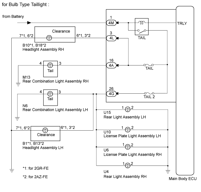
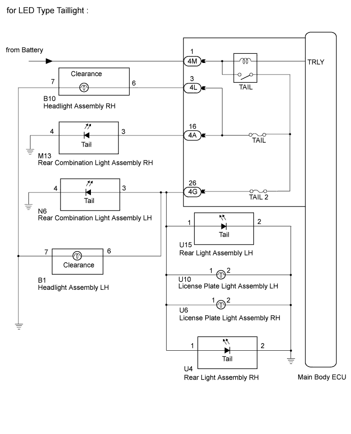
WIRING DIAGRAM
INSPECTION PROCEDURE
PROCEDURE
-
PERFORM ACTIVE TEST USING INTELLIGENT TESTER
-
Connect the intelligent tester to the DLC3.
-
Turn the engine switch on (IG).
-
Turn the intelligent tester on.
-
Enter the following menus: Body / Main Body / Active Test.
-
Check the operation.
Main Body Tester Display Test Part Control Range Diagnostic Note Taillight Relay Taillight relay ON/OFF - OK Taillight relay operates. (Taillights illuminate.)
NG 
CHECK HARNESS AND CONNECTOR (BATTERY - MAIN BODY ECU) Click here
OK 
PROCEED TO NEXT SUSPECTED AREA SHOWN IN PROBLEM SYMPTOMS TABLE Click here
-
-
CHECK HARNESS AND CONNECTOR (BATTERY - MAIN BODY ECU)
-
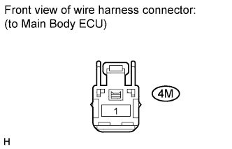
Disconnect the 4M main body ECU connector.
-
Measure the voltage according to the value(s) in the table below.
Standard Voltage Tester Connection Condition Specified Condition 4M-1 - Body ground Always 11 to 14 V
NG 
REPAIR OR REPLACE HARNESS OR CONNECTOR
OK
REPLACE MAIN BODY ECU Click here
-