WIPER AND WASHER SYSTEM Wiper and Washer Switch Circuit
DESCRIPTION
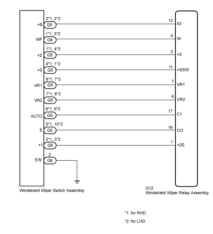
This circuit detects the state of the windshield wiper switch assembly (front wiper switch and front washer switch) and sends it to the windshield wiper relay assembly.
WIRING DIAGRAM
INSPECTION PROCEDURE
PROCEDURE
-
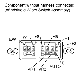
INSPECT WINDSHIELD WIPER SWITCH ASSEMBLY
-
for RHD
-
Remove the windshield wiper switch assembly Click here.
-
Measure the resistance according to the value(s) in the table below.
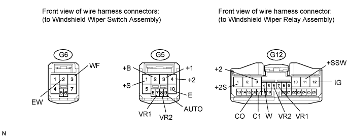
Standard Resistance Front Wiper Switch Tester Connection Switch Condition Specified Condition G5-2 (+1) - G5-4 (+S) OFF Below 1 Ω G5-2 (+1) - G5-3 (+B) MIST LO G5-3 (+B) - G5-1 (+2) HI G5-6 (AUTO) - G5-5 (E) AUTO Front Washer Switch Tester Connection Switch Condition Specified Condition G6-2 (EW) - G6-1 (WF) ON Below 1 Ω OFF 10 kΩ or higher Adjusting Ring*1 Tester Connection Condition Specified Condition G5-8 (VR1) - G5-7 (VR2) Adjusting ring changed from (+) side to (-) side 0 to 2.7 kΩ
-
-
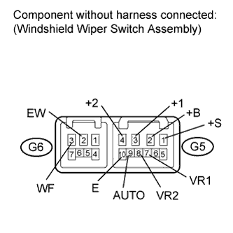
for LHD
-
Remove the windshield wiper switch assembly Click here.
-
Measure the resistance according to the value(s) in the table below.
Standard Resistance Front Wiper Switch Tester Connection Switch Condition Specified Condition G5-3 (+1) - G5-1 (+S) OFF Below 1 Ω G5-3 (+1) - G5-2 (+B) MIST LO G5-2 (+B) - G5-4 (+2) HI G5-9 (AUTO) - G5-10 (E) AUTO Front Washer Switch Tester Connection Switch Condition Specified Condition G6-2 (EW) - G6-3 (WF) ON Below 1 Ω OFF 10 kΩ or higher Adjusting Ring*1 Tester Connection Condition Specified Condition G5-7 (VR1) - G5-8 (VR2) Adjusting ring changed from (+) side to (-) side 0 to 2.7 kΩ Tech Tips
*1: The rain sensor sensitivity can be adjusted by the windshield wiper switch adjusting ring.
-
NG 
REPLACE WINDSHIELD WIPER SWITCH ASSEMBLY Click here
OK 
-
-
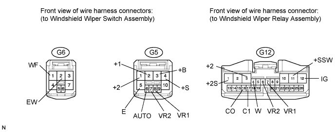
CHECK HARNESS AND CONNECTOR (WIPER SWITCH - WIPER RELAY AND BODY GROUND)
-
for RHD
-
Disconnect the G6 and G5 windshield wiper switch assembly connectors.
-
Disconnect the G12 windshield wiper relay assembly connector.
-
Measure the resistance according to the value(s) in the table below.
Standard Resistance Tester Connection Condition Specified Condition G5-3 (+B) - G12-12 (IG) Always Below 1 Ω G5-3 (+B) - Body ground Always 10 kΩ or higher G5-2 (+1) - G12-1 (+2S) Always Below 1 Ω G5-2 (+1) - Body ground Always 10 kΩ or higher G5-1 (+2) - G12-3 (+2) Always Below 1 Ω G5-1 (+2) - Body ground Always 10 kΩ or higher G5-4 (+S) - G12-11 (+SSW) Always Below 1 Ω G5-4 (+S) - Body ground Always 10 kΩ or higher G5-6 (AUTO) - G12-17 (C1) Always Below 1 Ω G5-6 (AUTO) - Body ground Always 10 kΩ or higher G5-5 (E) - G12-16 (CO) Always Below 1 Ω G5-5 (E) - Body ground Always 10 kΩ or higher G5-8 (VR1) - G12-7 (VR1) Always Below 1 Ω G5-8 (VR1) - Body ground Always 10 kΩ or higher G5-7 (VR2) - G12-6 (VR2) Always Below 1 Ω G5-7 (VR2) - Body ground Always 10 kΩ or higher G6-1 (WF) - G12-4 (W) Always Below 1 Ω G6-1 (WF) - Body ground Always 10 kΩ or higher G6-2 (EW) - Body ground Always Below 1 Ω
-
-
for LHD
-
Disconnect the G6 and G5 windshield wiper switch assembly connectors.
-
Disconnect the G12 windshield wiper relay assembly connector.
-
Measure the resistance according to the value(s) in the table below.
Standard Resistance Tester Connection Condition Specified Condition G5-2 (+B) - G12-12 (IG) Always Below 1 Ω G5-2 (+B) - Body ground Always 10 kΩ or higher G5-3 (+1) - G12-1 (+2S) Always Below 1 Ω G5-3 (+1) - Body ground Always 10 kΩ or higher G5-4 (+2) - G12-3 (+2) Always Below 1 Ω G5-4 (+2) - Body ground Always 10 kΩ or higher G5-1 (+S) - G12-11 (+SSW) Always Below 1 Ω G5-1 (+S) - Body ground Always 10 kΩ or higher G5-9 (AUTO) - G12-17 (C1) Always Below 1 Ω G5-9 (AUTO) - Body ground Always 10 kΩ or higher G5-10 (E) - G12-16 (CO) Always Below 1 Ω G5-10 (E) - Body ground Always 10 kΩ or higher G5-7 (VR1) - G12-7 (VR1) Always Below 1 Ω G5-7 (VR1) - Body ground Always 10 kΩ or higher G5-8 (VR2) - G12-6 (VR2) Always Below 1 Ω G5-8 (VR2) - Body ground Always 10 kΩ or higher G6-3 (WF) - G12-4 (W) Always Below 1 Ω G6-3 (WF) - Body ground Always 10 kΩ or higher G6-2 (EW) - Body ground Always Below 1 Ω
-
NG
REPAIR OR REPLACE HARNESS OR CONNECTOR
OK 
PROCEED TO NEXT SUSPECTED AREA SHOWN IN PROBLEM SYMPTOMS TABLE Click here
-