WIPER AND WASHER SYSTEM Rain Sensor Circuit
DESCRIPTION
The windshield wiper relay assembly receives a signal from the rain sensor to control the auto wiper system.
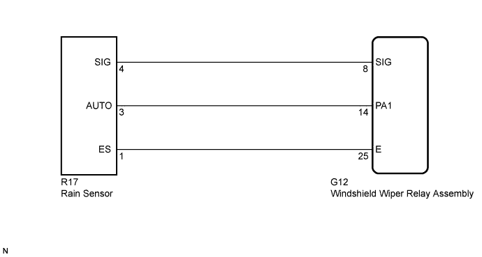
WIRING DIAGRAM
INSPECTION PROCEDURE
PROCEDURE
-
CHECK HARNESS AND CONNECTOR (WINDSHIELD WIPER RELAY ASSEMBLY - RAIN SENSOR)
-
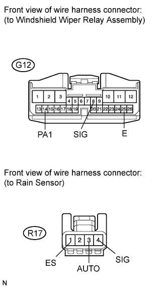
Disconnect the G12 windshield wiper relay assembly connector.
-
Disconnect the R17 rain sensor connector.
-
Measure the resistance according to the value(s) in the table below.
Standard Resistance Tester Connection Condition Specified Condition G12-8 (SIG) - R17-4 (SIG) Always Below 1 Ω R17-4 (SIG) - Body ground Always 10 kΩ or higher G12-14 (PA1) - R17-3 (AUTO) Always Below 1 Ω R17-3 (AUTO) - Body ground Always 10 kΩ or higher G12-25 (E) - R17-1 (ES) Always Below 1 Ω R17-1 (ES) - Body ground Always 10 kΩ or higher
NG 
REPAIR OR REPLACE HARNESS OR CONNECTOR
OK 
-
-
INSPECT WINDSHIELD WIPER RELAY ASSEMBLY
-
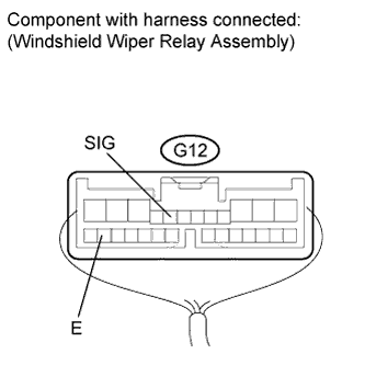
Reconnect the windshield wiper relay assembly connector.
-
Measure the voltage according to the value(s) in the table below.
Standard Voltage Tester Connection Condition Specified Condition G12-8 (SIG) - G12-25 (E) Engine switch on (IG) 7.5 to 8.5 V Result Result Proceed to OK A NG (for RHD) B NG (for LHD) C
B
REPLACE WINDSHIELD WIPER RELAY ASSEMBLY (for RHD) Click here
C
REPLACE WINDSHIELD WIPER RELAY ASSEMBLY (for LHD) Click here
A
-
-
INSPECT RAIN SENSOR
-
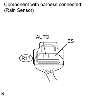
Reconnect the rain sensor connector.
-
Connect an oscilloscope to the automatic light control sensor connector.
-
Check for pulses.
OK Tester Connection Condition Specified Condition R17-3 (AUTO) - R17-1 (ES) Engine switch on (IG) Pulse generation
NG
REPLACE RAIN SENSOR Click here
OK 
PROCEED TO NEXT SUSPECTED AREA SHOWN IN PROBLEM SYMPTOMS TABLE Click here
-