OUTER MIRROR SWITCH (for LHD) INSPECTION

-
INSPECT OUTER MIRROR SWITCH ASSEMBLY
-
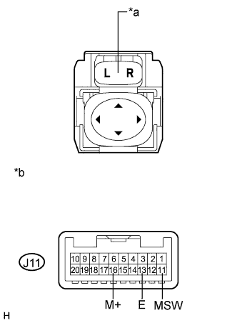
Text in Illustration *1 Component without harness connected
(Outer Mirror Switch Assembly)
*2 Mirror Select switch Check the switch functions.
-
For the L position of the mirror select switch:
Measure the resistance according to the value(s) in the table below.
Standard Resistance Tester Connection Switch Condition Specified Condition J11-16 (M+) - J11-13 (E) Mirror adjust switch pressed up 95 to 105 Ω Mirror adjust switch pressed down 446 to 493 Ω Mirror adjust switch pressed left 760 to 840 Ω Mirror adjust switch pressed right 237 to 262 Ω Mirror adjust switch not pressed 10 kΩ or higher J11-11 (MSW) - J11-13 (E) Mirror select switch L 95 to 105 Ω Mirror select switch off 10 kΩ or higher If the result is not as specified, replace the outer mirror switch assembly.
-
For the R position of the mirror select switch:
Measure the resistance according to the value(s) in the table below.
Standard Resistance Tester Connection Switch Condition Specified Condition J11-16 (M+) - J11-13 (E) Mirror adjust switch pressed up 95 to 105 Ω Mirror adjust switch pressed down 446 to 493 Ω Mirror adjust switch pressed left 760 to 840 Ω Mirror adjust switch pressed right 237 to 262 Ω Mirror adjust switch not pressed 10 kΩ or higher J11-11 (MSW) - J11-13 (E) Mirror select switch R Below 1 Ω Mirror select switch off 10 kΩ or higher If the result is not as specified, replace the outer mirror switch assembly.
-
-
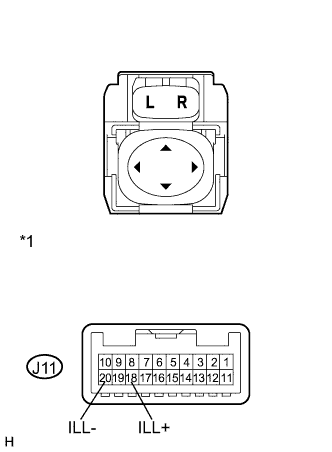
Text in Illustration *1 Component without harness connected
(Outer Mirror Switch)
Check that the LED illuminates.
-
Apply battery voltage to the outer mirror switch assembly and check that the LED illuminates.
OK Measurement Condition Specified Condition Battery positive (+) → J11-18 (ILL+)
Battery negative (-) → J11-20 (ILL-)
LED illuminates If the result is not as specified, replace the outer mirror switch assembly.
-
-
-
INSPECT OUTER MIRROR RETRACTABLE SWITCH
-
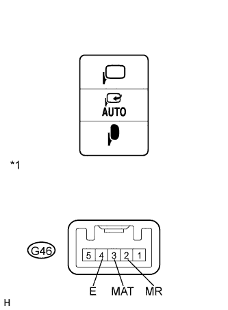
Text in Illustration *1 Component without harness connected
(Outer Mirror Retractable Switch)
Check that the switch functions.
-
Measure the resistance according to the value(s) in the table below.
Standard Resistance Tester Connection Switch Condition Specified Condition G46-3 (MAT) - G46-4 (E) AUTO position Below 1 Ω Except AUTO position 10 kΩ or higher G46-4 (E) - G46-2 (MR) Retract position Below 1 Ω Except retract position 10 kΩ or higher If the result is not as specified, replace the outer mirror retractable switch.
-
-
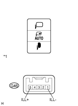
*1 Component without harness connected
(Outer Mirror Retractable Switch)
Check that the LED illuminates.
-
Apply battery voltage to the outer mirror retractable switch and check that the LED illuminates.
Measurement Condition Specified Condition Battery positive (+) → G46-5 (ILL+)
Battery negative (-) → G46-1 (ILL-)
LED illuminates If the result is not as specified, replace the outer mirror retractable switch.
-
-