OUTER REAR VIEW MIRROR REASSEMBLY

Tech Tips
-
Use the same procedure for both the RH and LH sides.
-
The procedure described below is for the LH side.
-
INSTALL OUTER MIRROR RETRACTOR
-
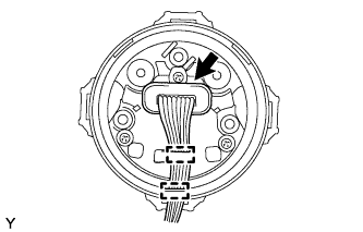
Install the wire harness
-
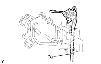
Text in Illustration *a Pink Marking Pass a new wire harness through the motor and frame sub-assembly from the top, and set the pink marking of the wire harness to the position shown in the illustration.
-
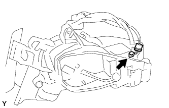
Connect the connector and install the cover.
-
-
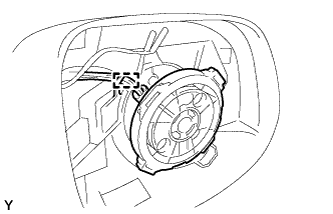
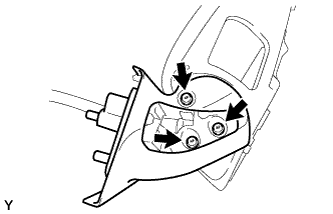
Install the motor and frame sub-assembly
-
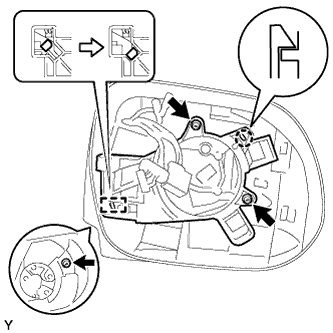
Engage the guide as shown in the illustration.
-
Engage the claw.
-
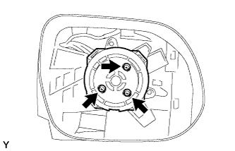
Install the motor and frame sub-assembly with the 3 screws.
-
-
Install the actuator
-
Connect the connector.
-
Install the cover and engage the 2 clamps.
-
Engage the clamp.
-
Install the actuator with the 3 screws.
-
-
Install the base plate
-
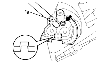
Text in Illustration *a Pink Marking Engage the clamp and guide.
-
Using "TORX" socket wrench T25, install the base plate with the new screw.
- Torque:
- 3.8 N*m { 39 kgf*cm, 34 in.*lbf }
-
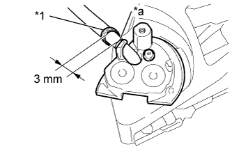
Text in Illustration *1 New Foam Tape *a Pink Marking Wrap new foam tape as shown in the illustration.
-
-
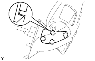
Install the base
-
Pass the wire harness through the base.
-
Using "TORX" socket wrench T25, install the base with 3 new screws.
- Torque:
- 3.8 N*m { 39 kgf*cm, 34 in.*lbf }
Note
When installing the base, check that the wire harness is not caught between the base and housing. Failure to do so may cause a short circuit.
-
-
Install the lower mirror cover
-
Engage the 4 claws and install the lower mirror cover.
-
-
Install the gasket
-
Set the mirror to the driving position.
-
Pass the wire harness through the new gasket.
-
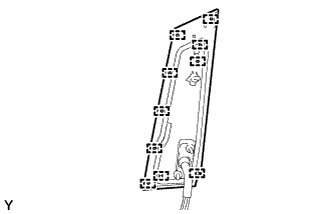
Engage the 10 guides and install the gasket.
-
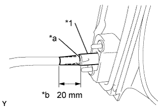
Text in Illustration *1 New Vinyl Tape *a Marking *b Length of taped wire harness portion extending from end of wire harness insertion hole of gasket Align the marking on the wire harness with the marking on the end of the wire harness insertion hole of the gasket as shown in the illustration.
-
Wrap new vinyl tape as shown in the illustration.
Note
Wrap the vinyl tape tightly around the wire harness to ensure that there are no gaps.
-
-
Install the adaptor (w/o memory)
-
Connect the connector of the shorter wire harness to the adapter.
-
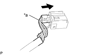
Text in Illustration *a Twisted wire harness Twist the longer wire harness as shown in the illustration and connect the connector to the adapter.
-
-
Install the connector (w/ memory)
-
Set the retainer to the unlock position.
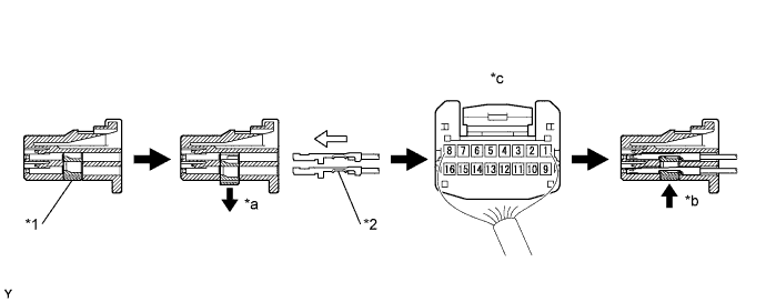
Text in Illustration *1 Retainer *2 Wire Harness Pin *a Retainer Unlock Position *b Retainer Lock Position *c Back View of Wire Harness Connector - - Wire Harness 1 2 3 4 5 6 7 8 Purple Black / Green
*1
Sky Blue Pink - - Red / White Black / Yellow 9 10 11 12 13 14 15 16 Brown Red Light Green White - - Gray Blue / Yellow
-
*1 : w/ heater
Note
-
When inserting the wire harness pins, compare with the connector that was cut off during removal to verify the insertion positions, and then make sure to insert the pins of the correct wire colors in the correct positions.
-
Make sure that the wire harness pins are securely locked in position and cannot be removed.
-
The wire harness pins cannot be removed after they have locked into place, so be absolutely certain to insert them in the correct positions.
-
-
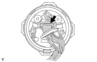
Push in the wire harness pins from the rear side of the connector until they lock into position.
-
Set the retainer to the lock position.
-
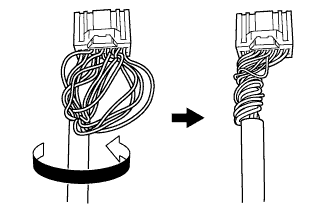
Twist the wire harness as shown in the illustration.
-
-