| DTC Code | DTC Name |
|---|---|
| Reverse Shift-linked Function of Power Mirrors does not Operate |
SYSTEM DESCRIPTION
When the reverse signal is sent from the ECM through the CAN communication line to the outer mirror control ECU assembly, the outer mirror control ECU assembly activates the reverse shift-linked function of the outer rear view mirrors assembly LH and RH.
The reverse shift-linked function will not activate when the mirror select switch is in the neutral position (off).
INSPECTION PROCEDURE
PROCEDURE
- Click here
CHECK CAN COMMUNICATION SYSTEM
-
Use the intelligent tester to check if the CAN communication system is functioning normally (Click here).
OK CAN communication DTC is not output.
- OKClick here
- NGClick here
-
- Click here
CHECK FOR DTC (P0705)
-
Connect the intelligent tester to the DLC3.
-
Turn the engine switch on (IG).
-
Turn the intelligent tester on.
-
Enter the following menus: Powertrain / Engine*1 or Engine and ECT*2 / DTC.
-
*1: for 2GR-FE
-
*2: for 2AZ-FE
-
-
Check if DTC P0705 is output.
OK DTC P0705 is not output. Result Result Proceed to OK A NG (for 2GR-FE) B NG (for 2AZ-FE) C
-
- Click here
CHECK POWER MIRROR CONTROL FUNCTION
-
Check that the mirror surface positions of the outer rear view mirror assembly LH and RH can be moved using the outer mirror switch assembly.
OK Mirror surface positions of the outer rear view mirror assembly LH and RH can be moved using the outer mirror switch assembly.
- OKClick here
- NGClick here
-
- Click here
READ VALUE USING INTELLIGENT TESTER (MIRROR POSITION SENSOR)
-
Enter the following menus: Body / Mirror / Data List.
-
Read the Data List according to the display on the intelligent tester.
Table 1. Mirror Tester Display Measurement Item/Range Normal Condition Diagnostic Note RH Mir Position Sensor V RH side mirror vertical sensor voltage / min: 0.49 V, max: 4.45 V Within range from 0.49 to 4.45 V - LH Mir Position Sensor V LH side mirror vertical sensor voltage / min: 0.49 V, max: 4.45 V Within range from 0.49 to 4.45 V - OK When the mirror control switch is operated to turn the mirror upward or downward, voltage changes within the range shown in the table above. Result Result Proceed to Mirrors operate normally A RH side mirror does not operate normally B LH side mirror does not operate normally C
-
- Click here
CHECK HARNESS AND CONNECTOR (OUTER REAR VIEW MIRROR RH - OUTER MIRROR CONTROL ECU)
-
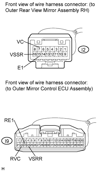
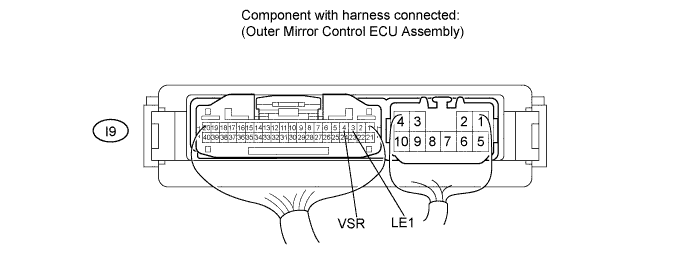
Disconnect the I9 connector from the outer mirror control ECU assembly.
-
Disconnect the I2 connector from the outer rear view mirror assembly RH.
-
Measure the resistance according to the value(s) in the table below.
Standard Resistance Tester Connection Condition Specified Condition I2-7 (VC) - I9-22 (RVC) Always Below 1 Ω I2-16 (VSSR) - I9-24 (VSRR) Always Below 1 Ω I2-15 (E1) - I9-23 (RE1) Always Below 1 Ω I9-22 (RVC) - Body ground Always 10 kΩ or higher I9-24 (VSRR) - Body ground Always 10 kΩ or higher I9-23 (RE1) - Body ground Always 10 kΩ or higher
- OKClick here
- NGClick here
-
- Click here
CHECK OUTER MIRROR CONTROL ECU ASSEMBLY (POWER SOURCE FOR MIRROR SURFACE POSITION SENSOR)
-
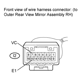
Reconnect the I9 connector to the outer mirror control ECU assembly.
-
Measure the voltage according to the value(s) in the table below.
Standard Voltage Tester Connection Condition Specified Condition I2-7 (VC) - I2-15 (E1) Engine switch on (IG) 5 V
- OKClick here
- NGClick here
-
- Click here
CHECK OUTER REAR VIEW MIRROR ASSEMBLY RH (MIRROR SURFACE POSITION SENSOR SIGNAL)
-
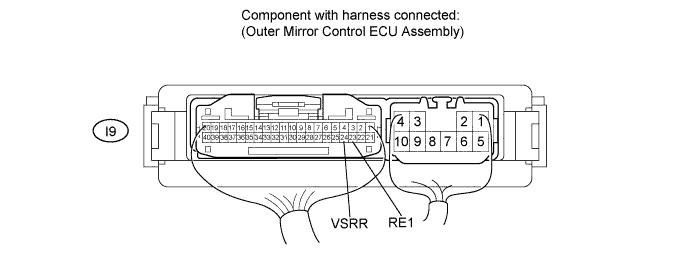
Reconnect the I2 connector to the outer rear view mirror assembly RH.
-
Turn the engine switch on (IG).
-
Measure the voltage according to the value(s) in the table below.
Standard Voltage Tester Connection Condition Specified Condition I9-24 (VSRR) - I9-23 (RE1) Mirror surface position: turned fully downward → turned fully upward 0.49 V → 4.45 V
- OKClick here
- NGClick here
-
- Click here
CHECK HARNESS AND CONNECTOR (OUTER REAR VIEW MIRROR LH - OUTER MIRROR CONTROL ECU)
-
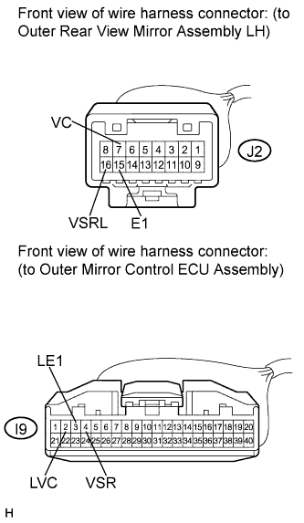
Disconnect the I9 connector from the outer mirror control ECU assembly.
-
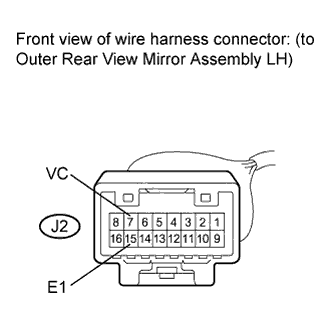
Disconnect the J2 connector from the outer rear view mirror assembly LH.
-
Measure the resistance according to the value(s) in the table below.
Standard Resistance Tester Connection Condition Specified Condition J2-7 (VC) - I9-2 (LVC) Always Below 1 Ω J2-16 (VSRL) - I9-4 (VSR) Always Below 1 Ω J2-15 (E1) - I9-3 (LE1) Always Below 1 Ω I9-2 (LVC) - Body ground Always 10 kΩ or higher I9-4 (VSR) - Body ground Always 10 kΩ or higher I9-3 (LE1) - Body ground Always 10 kΩ or higher
- OKClick here
- NGClick here
-
- Click here
CHECK OUTER MIRROR CONTROL ECU ASSEMBLY (POWER SOURCE FOR MIRROR SURFACE POSITION SENSOR)
-
Reconnect the I9 connector to the outer mirror control ECU assembly.
-
Turn the engine switch on (IG).
-
Measure the voltage according to the value(s) in the table below.
Standard Voltage Tester Connection Condition Specified Condition J2-7 (VC) - J2-15 (E1) Engine switch on (IG) 5 V
- OKClick here
- NGClick here
-
- Click here
CHECK OUTER REAR VIEW MIRROR ASSEMBLY LH (MIRROR SURFACE POSITION SENSOR SIGNAL)
-
Reconnect the J2 connector to the outer rear view mirror assembly LH.
-
Measure the voltage according to the value(s) in the table below.
Standard Voltage Tester Connection Condition Specified Condition I9-4 (VSR) - I9-3 (LE1) Mirror surface position: turned fully downward → turned fully upward 0.49 V → 4.45 V
- OKClick here
- NGClick here
-
- Click here
GO TO CAN COMMUNICATION SYSTEMClick here
- Click here
GO TO SFI SYSTEM (DTC P0705)Click here
- Click here
GO TO OTHER FLOW CHART (Power Mirror cannot be Adjusted with Power Mirror Switch)Click here
- Click here
REPLACE OUTER MIRROR CONTROL ECU ASSEMBLYClick here
- Click here
REPAIR OR REPLACE HARNESS OR CONNECTOR (OUTER REAR VIEW MIRROR RH - OUTER MIRROR CONTROL ECU)
- Click here
REPLACE OUTER MIRROR CONTROL ECU ASSEMBLYClick here
- Click here
REPLACE OUTER REAR VIEW MIRROR ASSEMBLY RHClick here
- Click here
REPLACE OUTER MIRROR CONTROL ECU ASSEMBLYClick here
- Click here
REPAIR OR REPLACE HARNESS OR CONNECTOR (OUTER REAR VIEW MIRROR LH - OUTER MIRROR CONTROL ECU)
- Click here
REPLACE OUTER MIRROR CONTROL ECU ASSEMBLYClick here
- Click here
REPLACE OUTER REAR VIEW MIRROR ASSEMBLY LHClick here
- Click here
REPLACE OUTER MIRROR CONTROL ECU ASSEMBLYClick here
- Click here
GO TO CONTINUOUSLY VARIABLE TRANSAXLE SYSTEM (DTC P0705)Click here