BACK DOOR ADJUSTMENT

Tech Tips
-
Use the same procedure for the RH side and the LH side.
-
The following procedure is for the LH side.
-
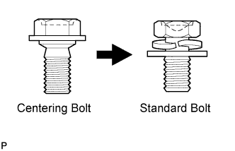
Centering bolts are used to mount the door hinge to the vehicle body and door. The door cannot be adjusted with the centering bolts installed on it. Substitute the centering bolts with standard bolts (with washers) when making adjustments.
-
Specified torque for standard bolts is shown in the standard bolt chart Click here.
-
PRECAUTION
Note
-
For the glass hatch type, if the back door adjustment is performed, the location of the axis of the rear wiper motor assembly will change, causing the wiping angle to change. Be sure to remove and install the rear wiper motor assembly using the centering jig.
-
Do not open the glass hatch before installing the rear wiper link pivot.
-
-
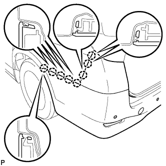
REMOVE REAR BUMPER ASSEMBLY
-
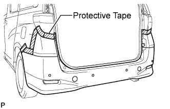
Put protective tape around the rear bumper assembly.
-
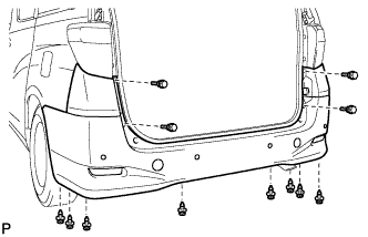
Remove the 4 bolts.
-
Using a clip remover, remove the 8 clips.
-
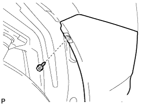
Remove the screw.
Tech Tips
Use the same procedure for the RH side and LH side.
-
Disengage the 8 claws.
Tech Tips
Use the same procedure for the RH side and LH side.
-
Disconnect the connector and remove the rear bumper assembly.
-
-
REMOVE BACK DOOR STRIKER COVER
-
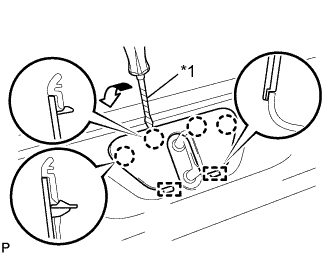
Text in Illustration *1 Protective Tape Using a screwdriver, disengage the 4 claws and 2 guides, and remove the back door striker cover.
Tech Tips
Tape the screwdriver tip before use.
-
-
REMOVE BACK DOOR SCUFF PLATE
-
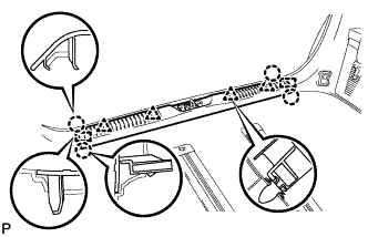
Remove the 4 claws, 4 clips and 2 guides, and remove the back door scuff plate.
-
-
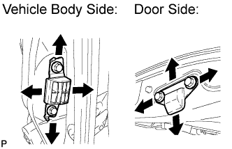
ADJUST BACK DOOR PANEL SUB-ASSEMBLY
-
Before adjusting the upper end of the back door up and down or left and right, loosen the bolts.
-
Tighten the body side hinge after the adjustment.
- Torque:
- 19 N*m { 194 kgf*cm, 14 ft.*lbf }
-

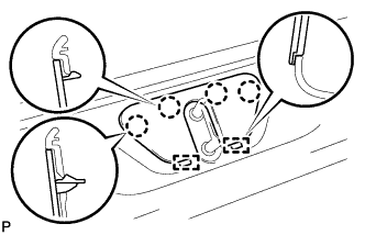
Adjust the striker position by slightly loosening the striker mounting screws and hitting the striker with a plastic hammer.
-
Tighten the striker mounting screws after the adjustment.
- Torque:
- 23 N*m { 235 kgf*cm, 17 ft.*lbf }
-
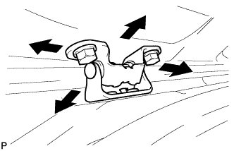
After adjusting the back door position, adjust the positions of the back door side female and male stoppers.
- Torque:
- 7.5 N*m { 77 kgf*cm, 66 in.*lbf }
-
-
INSTALL BACK DOOR SCUFF PLATE
-
Engage the 2 guides, 4 clips and 4 claws to install the back door scuff plate.
-
-
INSTALL BACK DOOR STRIKER COVER
-
Engage the 2 guides and 4 claws to install the back door striker cover.
-
-
INSTALL REAR BUMPER ASSEMBLY
-
Connect the connector.
-
Engage the 8 claws.
Tech Tips
Use the same procedure for the RH side and LH side.
-
Install the screw.
Tech Tips
Use the same procedure for the RH side and LH side.
-
Install the rear bumper assembly with the 4 bolts and 8 clips.
-