BACK DOOR DISASSEMBLY

-
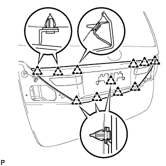
REMOVE BACK DOOR CENTER GARNISH
-
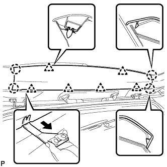
Using a moulding remover C, disengage the 6 clips and 4 claws, and remove the back door center garnish.
-
-
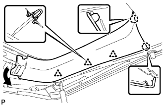
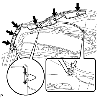
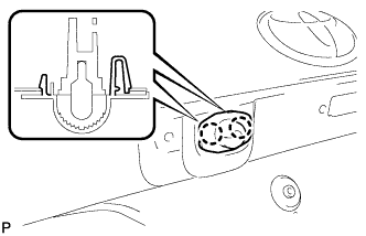
REMOVE REAR WINDOW SIDE GARNISH LH (w/o Power Back Door)
-
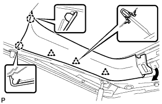
Disengage the 3 clips and 2 claws, and remove the rear window side garnish LH.
-
-
REMOVE BACK DOOR NO. 2 SERVICE HOLE COVER (w/ Power Back Door)
-
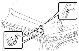
Disengage the 3 claws and remove the back door No. 2 service hole cover.
-
-
REMOVE REAR WINDOW SIDE GARNISH LH (w/ Power Back Door)
-
Disengage the 3 clips and 2 claws, and remove the rear window side garnish LH.
-
-
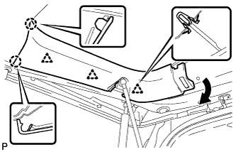
REMOVE REAR WINDOW SIDE GARNISH RH
-
Disengage the 3 clips and 2 claws, and remove the rear window side garnish RH.
-
-
REMOVE BACK DOOR INSIDE HANDLE
-
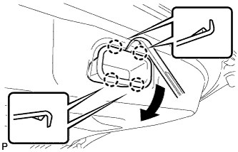
Using a moulding remover, disengage the 4 claws as shown in the illustration and remove the back door inside handle.
-
-
REMOVE SWITCH BEZEL (w/ Power Back Door)
-
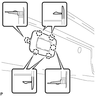
Disengage the 6 claws and remove the switch bezel.
-
-
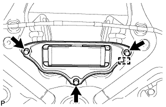
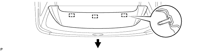
REMOVE BACK DOOR TRIM BOARD ASSEMBLY
-
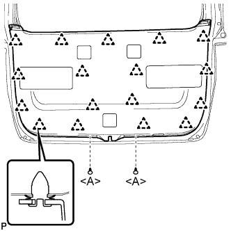
Using a clip remover, remove the 2 clips <A>.
-
Disengage the 17 clips and remove the back door trim board assembly.
Note
w/ Power Back Door:To prevent the parts from being damaged, make sure that the back door trim board assembly does not get caught on the power back door closer switch assembly during removal.
-
-
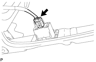
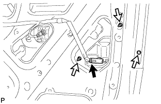
REMOVE BACK DOOR LOCK ASSEMBLY (w/o Easy Closer)
-
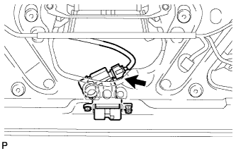
Disconnect the connector.
-
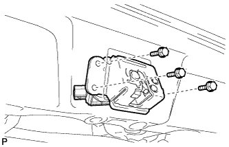
Remove the 3 bolts and back door lock assembly.
-
-
REMOVE BACK DOOR LOCK ASSEMBLY (w/ Easy Closer)
-
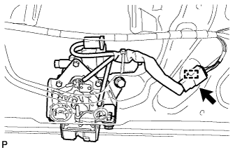
Disconnect the connector.
-
Disengage the clamp.
-
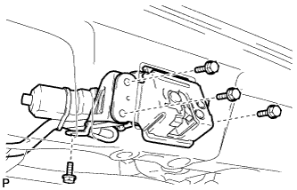
Remove the 4 bolts and back door lock assembly.
-
-
REMOVE POWER BACK DOOR CLOSER SWITCH ASSEMBLY (w/ Power Back Door)
-
Disconnect the connector.
-
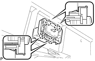
Disengage the 4 claws and remove the power back door closer switch assembly.
-
-
DISCONNECT POWER BACK DOOR ROD (w/ Power Back Door)
-
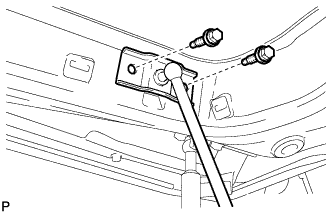
Remove the 2 bolts and disconnect the power back door rod.
-
-
REMOVE BACK DOOR SIDE MALE STOPPER LH
-
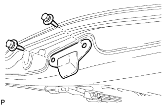
Remove the 2 bolts and back door side male stopper LH.
-
-
REMOVE BACK DOOR SIDE MALE STOPPER RH
Tech Tips
Use the same procedure for the RH side and LH side.
-
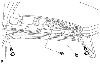
REMOVE POWER BACK DOOR TOUCH SENSOR ASSEMBLY LH (w/ Power Back Door)
-
Disconnect the connector.
-
Remove the 6 bolts.
-
Disengage the 2 clips to remove the power back door touch sensor assembly.
-
-
REMOVE POWER BACK DOOR TOUCH SENSOR ASSEMBLY RH (w/ Power Back Door)
Tech Tips
Use the same procedure for the RH side and LH side.
-
REMOVE BACK DOOR WEIGHT
-
Remove the 3 bolts.
-
Disengage the guide and remove the back door weight.
-
-
REMOVE BACK DOOR PANEL CUSHION (for Upper Side)
-
Disengage the claw and remove the back door panel cushion.
Tech Tips
Use the same procedure for the RH side and LH side.
-
-
REMOVE BACK DOOR PANEL CUSHION (for Lower Side)
-
Disengage the claw and remove the back door panel cushion.
Tech Tips
Use the same procedure for the RH side and LH side.
-
-
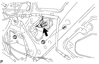
REMOVE BACK DOOR OPENER SWITCH ASSEMBLY
-
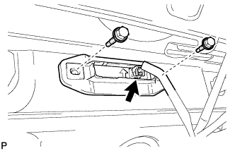
Disconnect the connector.
-
Remove the 2 bolts and back door opener switch.
-
-
REMOVE TELEVISION CAMERA ASSEMBLY (w/ Parking Assist Monitor System)
-
Disconnect the connector.
-
Remove the 2 screws.
-
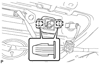
Disengage the 2 clamps and remove the rear television camera assembly.
-
-
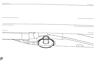
REMOVE REAR WIPER ARM AND BLADE ASSEMBLY
-
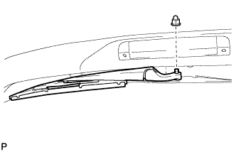
Remove the nut and the rear wiper arm and blade assembly.
-
-
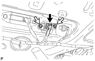
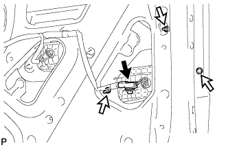
REMOVE REAR WIPER MOTOR ASSEMBLY
-
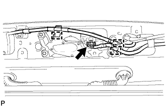
Disconnect the connector.
-
Disengage the 3 clamps.
-
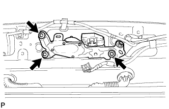
Remove the 3 bolts and the rear wiper motor assembly.
-
-
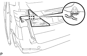
REMOVE NO. 1 REAR SPOILER COVER
-
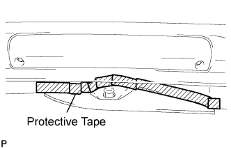
Put protective tape around the No. 1 rear spoiler cover.
-
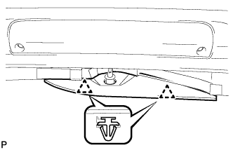
Disengage the 2 clips and remove the rear No. 1 spoiler cover.
-
-
REMOVE REAR WIPER MOTOR GROMMET
-
Remove the rear wiper motor grommet.
-
-
REMOVE REAR LIGHT ASSEMBLY LH (for ALPHARD)
-
Disconnect the connector.
-
Remove the 3 nuts.
-
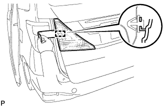
Using a moulding remover, disengage the guide and remove the rear light assembly.
-
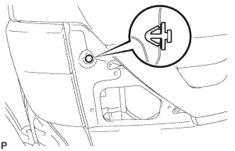
Remove the clip from the body.
-
-
REMOVE REAR LIGHT ASSEMBLY RH (for ALPHARD)
Tech Tips
Use the same procedure for the RH side and LH side.
-
REMOVE REAR LIGHT ASSEMBLY WITH COVER LH (for VELLFIRE)
-
Disconnect the connector.
-
Remove the 3 nuts.
-
Using a moulding remover, disengage the guide and remove the rear light assembly with cover.
-
Remove the clip from the body.
-
-
REMOVE REAR LIGHT ASSEMBLY WITH COVER RH (for VELLFIRE)
Tech Tips
Use the same procedure for the RH side and LH side.
-
REMOVE BACK DOOR OUTSIDE GARNISH SUB-ASSEMBLY
-
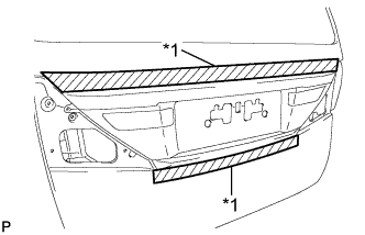
Text in Illustration *1 Protective Tape Put protective tape around the back door outside garnish sub-assembly.
-
Disconnect the connector and remove the 2 nuts.
Tech Tips
Use the same procedure for the RH side and LH side.
-
Disengage the 11 clips and remove the back door outside garnish sub-assembly.
-
Remove the 9 clips (luggage compartment door moulding clip) and 2 clips (back door outside garnish clip) from the buck door outside garnish sub-assembly.
-
-
REMOVE LICENSE PLATE LIGHT ASSEMBLY
-
Disconnect the connector.
-
Disengage the 2 claws and remove the license plate light assembly.
-
-
REMOVE REAR SPOILER ASSEMBLY
-
Disconnect the connector and washer hose.
-
Remove the 2 hole plugs.
-
Remove the 4 bolts.
-
Disengage the 3 pins to remove the rear spoiler assembly.
-