POWER SLIDE DOOR MOTOR REMOVAL

-
REMOVE REAR DOOR SCUFF PLATE
-
Captain type rear seat:
-
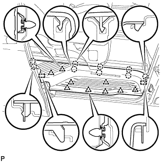
Disengage the 9 claws, 9 clips and 2 guides, and remove the rear door scuff plate RH.
-
-
Tip-up type rear seat:
-
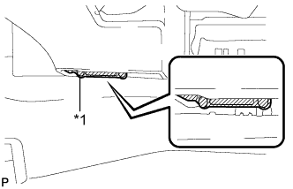
Text in Illustration *1 Protective Tape Apply protective tape to the bottom of the seat as shown in the illustration.
-
Using the slide lever, slide the rear No. 1 seat to the rearmost position.
-
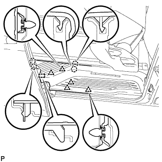
Disengage the 4 clips, 5 claws and guide on the front side of the scuff plate as shown in the illustration.
Note
To prevent damage to the scuff plate, make sure not to use excessive force when disengaging the clips, claws and guide.
-
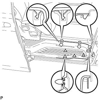
Using the reclining lever or foot-operated walk-in pedal, tip up the rear No. 1 seat and slide it to the foremost position.
-
Disengage the 5 clips, 4 claws and guide on the rear side of the scuff plate as shown in the illustration, and remove the rear door scuff plate RH.
Note
To prevent damage to the scuff plate, make sure not to use excessive force when disengaging the clips, claws and guide.
-
-
-
REMOVE SIDE STEP SUPPORT REAR
-
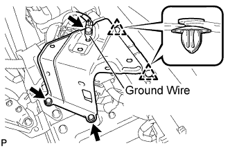
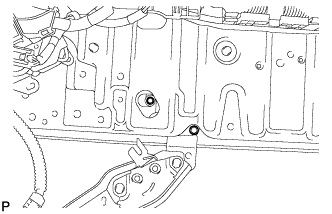
Remove the bolt and disconnect the ground wire.
-
Remove the 2 bolts.
-
Turn back the floor carpet.
-
Using a clip remover, disengage the 2 clips and remove the rear side step support.
-
-
DISCONNECT REAR DOOR NO. 1 WIRE
-
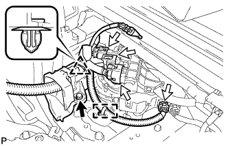
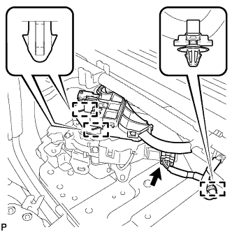
Disconnect each connector.
-
Remove the bolt.
-
Disengage the clamp.
-
Disengage the clip and disconnect the rear door No. 1 wire.
-
-
REMOVE SLIDE DOOR OPEN STRIKER
-
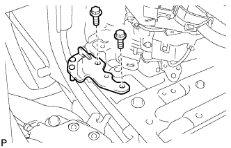
Remove the 2 bolts and slide door open striker.
-
-
REMOVE SLIDE DOOR LOWER RAIL PLATE
-
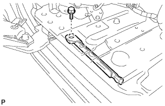
Remove the bolt and slide door lower rail plate.
-
-
REMOVE SLIDE DOOR MOTOR UNIT
-
Disconnect the connector.
-
Disengage the clamp.
-
Disengage the 2 clamps and connector holder.
-
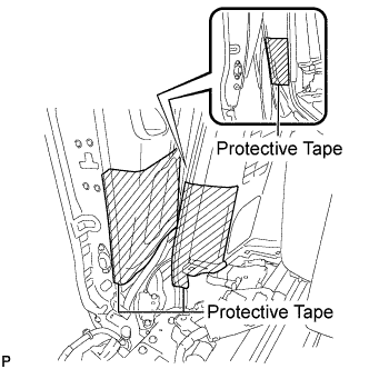
Put protective tape as shown in the illustration.
-
Move the slide door so that the 2 bolts can be seen.
-

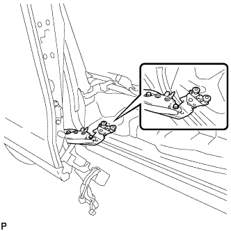
Remove the 2 bolts and disconnect the slide door lower roller assembly.
-
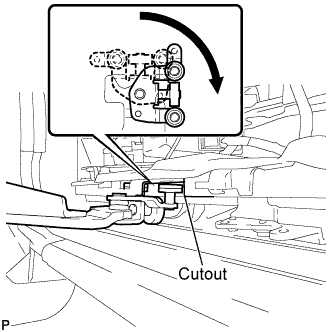
Turn the roller of the slide door lower roller assembly as shown in the illustration to remove it through the cutout of the slide door lower rail.
Note
To prevent the slide door from being dropped, deformed or damaged, make sure that there are enough people available to assist when performing this operation.
-
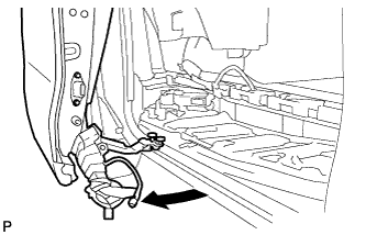
Pull the lower part of the slide door toward the outside of the vehicle as shown in the illustration so that the slide door motor unit can be removed.
Note
-
To prevent the slide door from being dropped, deformed or damaged, make sure that there are enough people available to assist when performing this operation.
-
Do not pull the slide door excessively. Otherwise, the slide door upper roller assembly or slide door upper rail may be deformed or damaged.
-
-
Move the slide door to its fully open position.
-
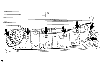
Remove the 7 bolts.
-
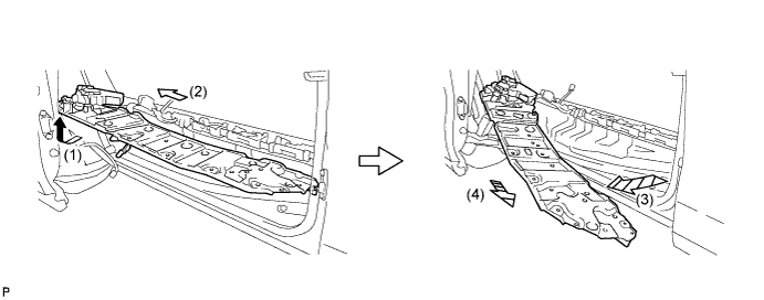
Remove the slide door motor unit as shown in the illustration.
-
Temporarily set the rollers of the slide door lower roller assembly to the position shown in the illustration.
Note
To prevent the slide door from being dropped, make sure to hold it.
-