POWER MIRROR CONTROL SYSTEM (w/ Memory) AUTO Power Retract Mirrors do not operate
DESCRIPTION
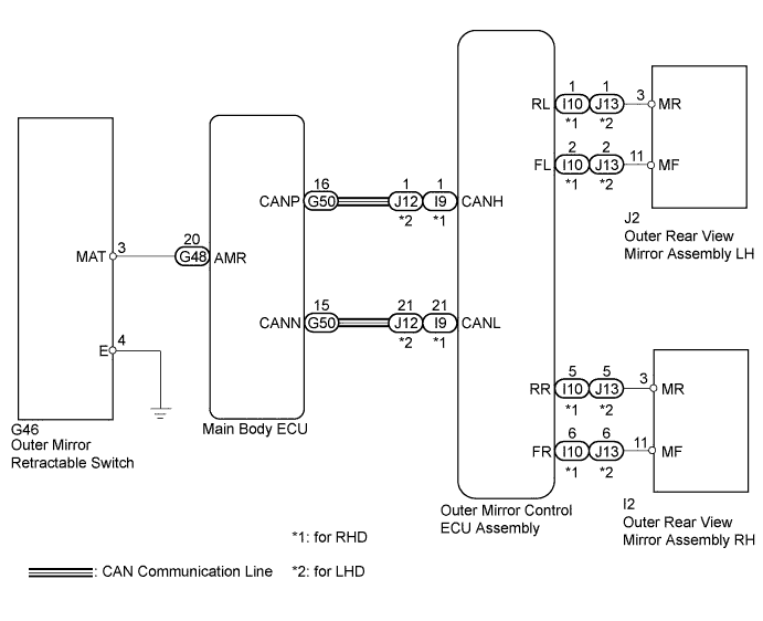
This circuit is used for the signals from the outer mirror retractable switch.
The outer mirror retractable switch sends a voltage signal to the main body ECU in accordance with switch operation (switch input signal). The main body ECU uses CAN communication to send this information to the outer mirror control ECU assembly, which then controls the mirrors.
When the outer mirror control ECU assembly receives a door lock output signal from the main body ECU while the power retract mirror switch is in the AUTO position, the outer mirror control ECU assembly operates the retract motors built into the outer rear view mirrors to retract or return the mirrors.
WIRING DIAGRAM
INSPECTION PROCEDURE
PROCEDURE
-
CHECK SMART ENTRY AND START SYSTEM (ENTRY FUNCTION)
-
Check the smart entry and start system (entry function) Click here.
OK Smart entry and start system (entry function) is normal.
NG 
GO TO SMART ENTRY AND START SYSTEM (PROBLEM SYMPTOMS TABLE) Click here
OK 
-
-
CHECK POWER RETRACT MIRROR FUNCTION (MANUAL FUNCTION)
-
Check the power retract mirror function (manual function) Click here.
OK Power retract mirror function (manual function) is normal.
NG
GO TO OTHER FLOW CHART Click here
OK
-
-
READ VALUE USING INTELLIGENT TESTER
-
Connect the intelligent tester to the DLC3.
-
Turn the engine switch on (IG).
-
Turn the intelligent tester on.
-
Enter the following menus: Body / Main Body / Data List.
-
Read the Data List according to the display on the intelligent tester.
Main Body Tester Display Measurement Item/Range Normal Condition Diagnostic Note Auto Mirror SW Outer mirror retractable switch signal / ON or OFF ON: Outer mirror retractable switch in AUTO position
OFF: Outer mirror retractable switch except AUTO position
- ON On the intelligent tester screen, ON or OFF is displayed according to the table above.
NG 
INSPECT OUTER MIRROR RETRACTABLE SWITCH Click here
OK
-
-
REPLACE OUTER MIRROR CONTROL ECU ASSEMBLY
-
Replace the outer mirror control ECU assembly Click here.
NEXT
-
-
CHECK POWER RETRACT MIRROR FUNCTION (AUTO ELECTRIC RETRACT FUNCTION)
-
Check the auto electric retract function Click here.
OK Auto electric retract function is normal.
NG
REPLACE MAIN BODY ECU Click here
OK 
END (OUTER MIRROR CONTROL ECU ASSEMBLY IS DEFECTIVE)
-
-
INSPECT OUTER MIRROR RETRACTABLE SWITCH
-
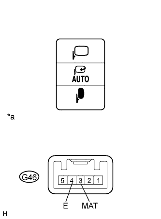
Text in Illustration *a Component without harness connected
(Outer Mirror Retractable Switch)
Remove the outer mirror retractable switch Click here for RHD, Click here for LHD).
-
Measure the resistance according to the value(s) in the table below.
Standard Resistance Tester Connection Switch Condition Specified Condition G46-3 (MAT) - G46-4 (E) AUTO position Below 1 Ω Except AUTO position 10 kΩ or higher Result Result Proceed to OK A NG (for RHD) B NG (for LHD) C
B
REPLACE OUTER MIRROR RETRACTABLE SWITCH Click here
C
REPLACE OUTER MIRROR RETRACTABLE SWITCH Click here
A
-
-
CHECK HARNESS AND CONNECTOR (MAIN BODY ECU - POWER RETRACT MIRROR SWITCH)
-
Disconnect the main body ECU connector.
-
Measure the resistance according to the value(s) in the table below.
Standard Resistance Tester Connection Condition Specified Condition G48-20 (AMR) - G46-3 (MAT) Always Below 1 Ω G48-20 (AMR) - Body ground Always 10 kΩ or higher G46-4 (E) - Body ground Always Below 1 Ω
NG
REPAIR OR REPLACE HARNESS OR CONNECTOR (MAIN BODY ECU - OUTER MIRROR RETRACTABLE SWITCH)
OK
REPLACE MAIN BODY ECU Click here
-