HOOD LOCK CONTROL CABLE ASSEMBLY INSTALLATION

-
INSTALL HOOD LOCK CONTROL CABLE ASSEMBLY (for RHD)
-
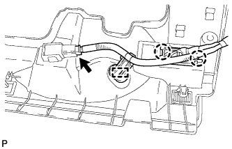
Pass the hood lock control cable assembly into the engine compartment.
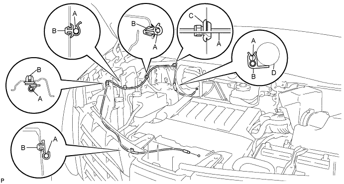
Area Part Name Area Part Name A Hood lock control cable C Hood cable grommet B Clamp D Wire harness -
Pass the cable through the upper radiator support.
-
Connect the clamps as shown in the illustration.
-
-
INSTALL HOOD LOCK CONTROL CABLE ASSEMBLY (for LHD)
-
Pass the hood lock control cable assembly into the engine compartment.
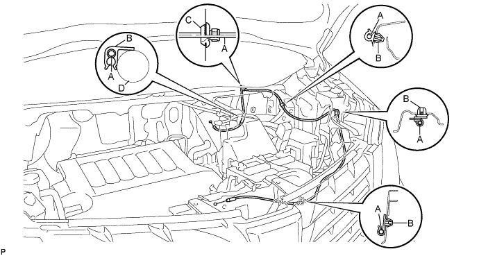
Area Part Name Area Part Name A Hood lock control cable C Hood cable grommet B Clamp - - -
Pass the cable through the upper radiator support.
-
Connect the clamps as shown in the illustration.
-
-
INSTALL HOOD LOCK CONTROL LEVER SUB-ASSEMBLY (for RHD)
-
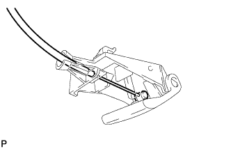
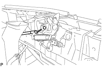
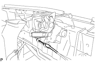
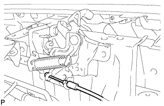
Connect the hood lock control cable to the hood lock control lever sub-assembly.
-
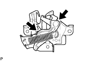
Engage the 3 claws to install the hood lock control lever sub-assembly.
-
-
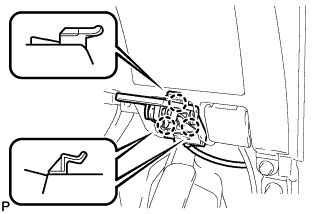
INSTALL HOOD LOCK CONTROL LEVER SUB-ASSEMBLY (for LHD)
-
Connect the hood lock control cable to the hood lock control lever sub-assembly.
-

Engage the 3 claws to install the hood lock control lever sub-assembly.
-
-
INSTALL NO. 1 INSTRUMENT PANEL UNDER COVER SUB-ASSEMBLY (for RHD)
-
Engage the 2 claws and DLC3.
-
Engage the clamp.
-
Connect the connector.
-

Engage the 2 claws and 2 guides.
Note
Make sure that the claws are fully engaged.
-
Install the No. 1 instrument panel under cover sub-assembly with the 2 screws <B>.
-
-
INSTALL NO. 1 INSTRUMENT PANEL UNDER COVER SUB-ASSEMBLY (for LHD)
-
Engage the clamp.
-
Connect each connector.
-

Engage the 2 claws and guide.
Note
Make sure that the claws are fully engaged.
-
Install the No. 1 instrument panel under cover sub-assembly with the 2 screws <B>.
-
-
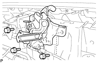
INSTALL HOOD LOCK ASSEMBLY (for LHD)
-
w/o Engine Hood Courtesy Switch:
-
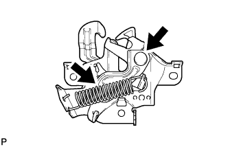
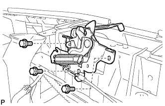
Apply MP grease to the sliding areas of the lock.
-
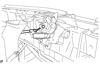
Connect the hood lock control cable.
-
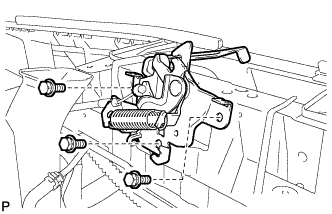
Install the hood lock assembly with the 3 bolts.
- Torque:
- 7.5 N*m { 77 kgf*cm, 66 in.*lbf }
-
-
w/ Engine Hood Courtesy Switch:
-
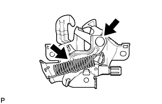
Apply MP grease to the sliding areas of the lock.
-
Connect the hood lock control cable.
-
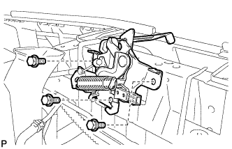
Install the hood lock assembly with the 3 bolts.
- Torque:
- 7.5 N*m { 77 kgf*cm, 66 in.*lbf }
-
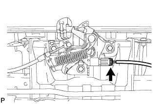
Connect the connector.
-
-
-
INSTALL HOOD LOCK ASSEMBLY (for RHD)
-
for ALPHARD:
-
Apply MP grease to the sliding areas of the lock.
-
Connect the hood lock control cable.
-
Install the hood lock assembly with the 3 bolts.
- Torque:
- 7.5 N*m { 77 kgf*cm, 66 in.*lbf }
-
-
for VELLFIRE:
-
Apply MP grease to the sliding areas of the lock.
-
Connect the hood lock control cable.
-
Install the hood lock assembly with the 3 bolts.
- Torque:
- 7.5 N*m { 77 kgf*cm, 66 in.*lbf }
-
-
-
INSTALL RADIATOR COVER SUB-ASSEMBLY (for ALPHARD)
-
Install the radiator cover sub-assembly with the 4 clips.
-
-
INSTALL RADIATOR COVER SUB-ASSEMBLY (for VELLFIRE)
-
Install the radiator cover sub-assembly with the 4 clips.
-
-
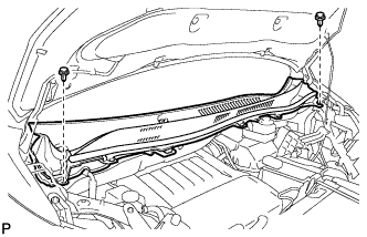
INSTALL OUTER COWL TOP PANEL
-
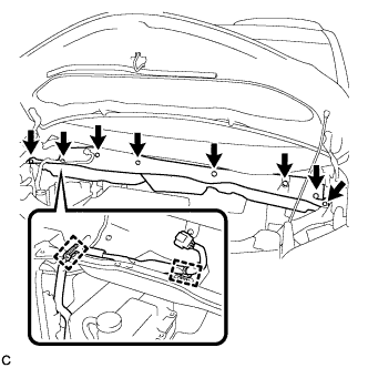
Install the outer cowl top panel with the 8 bolts.
- Torque:
- 8.8 N*m { 90 kgf*cm, 78 in.*lbf }
-
Connect the 2 clamps to the outer cowl top panel.
-
Remove the protective tape.
-
-
INSTALL BRAKE MASTER CYLINDER RESERVOIR WITH BRACKET
-
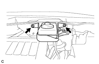
Install the brake master cylinder reservoir with bracket to the outer cowl top panel with the 2 nuts.
- Torque:
- 6.5 N*m { 66 kgf*cm, 58 in.*lbf }
-
-
INSTALL WINDSHIELD WIPER MOTOR AND LINK ASSEMBLY
-
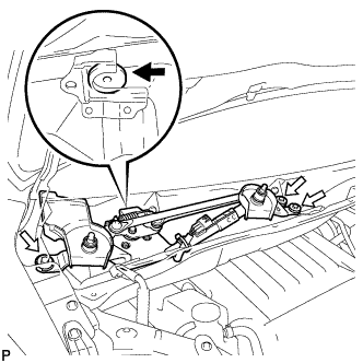
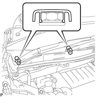
Install the windshield wiper motor and link assembly with the 3 bolts as shown in the illustration.
- Torque:
- 5.5 N*m { 56 kgf*cm, 49 in.*lbf }
-
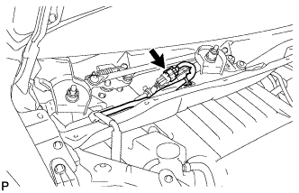
Connect the connector.
-
-
INSTALL COWL TOP VENTILATOR LOUVER SUB-ASSEMBLY
-
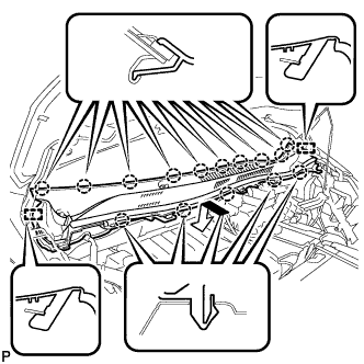
Engage the 15 claws and 2 guides to install the cowl top ventilator louver sub-assembly as shown in the illustration.
-
Install the 2 clips.
-
-
INSTALL FRONT WIPER ARM AND BLADE ASSEMBLY RH
-
Operate the wiper and stop the windshield wiper motor at the automatic stop position.
-
When reusing the front wiper arm and blade assembly RH:
-
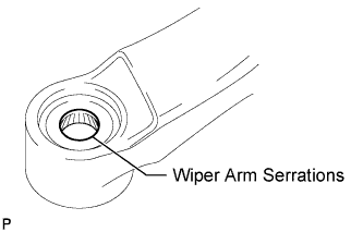
Clean the wiper arm serrations.
-
-
When reusing the windshield wiper link assembly:
-
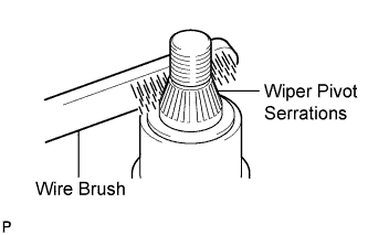
Clean the wiper pivot serrations with a wire brush.
-
-
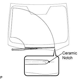
Install the front wiper arm and blade assembly RH with the nut to the position shown in the illustration.
- Torque:
- 24 N*m { 245 kgf*cm, 18 ft.*lbf }
-
-
INSTALL FRONT WIPER ARM AND BLADE ASSEMBLY LH
-
When reusing the front wiper arm and blade assembly LH:
-
Clean the wiper arm serrations.
-
-
When reusing the windshield wiper link assembly:
-
Clean the wiper pivot serrations with a wire brush.
-
-
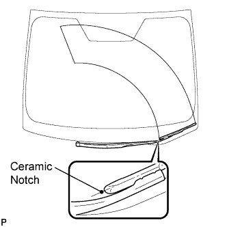
Install the front wiper arm and blade assembly LH with the nut to the position shown in the illustration.
- Torque:
- 24 N*m { 245 kgf*cm, 18 ft.*lbf }
-
Operate the front wipers while spraying washer fluid onto the windshield. Make sure that the front wipers function properly and the wipers do not come into contact with the vehicle body.
-
-
INSTALL WINDSHIELD WIPER ARM COVER
-
Engage the 2 claws to install the 2 windshield wiper arm covers.
-
-
INSPECT HOOD SUB-ASSEMBLY
-
Check that the clearance measurements of areas A through H are within each standard range.
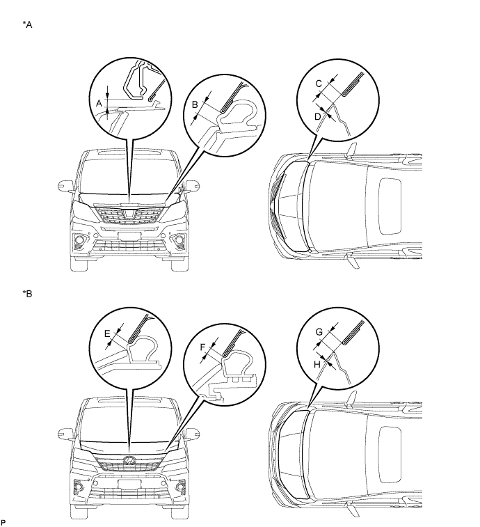
Text in Illustration *A for ALPHARD *B for VELLFIRE Standard Clearance Area Measurement Area Measurement A 5.9 to 9.9 mm (0.232 to 0.390 in.) E 2.2 to 6.2 mm (0.0866 to 0.244 in.) B 3.4 to 7.4 mm (0.134 to 0.291 in.) F 2.3 to 6.3 mm (0.0906 to 0.248 in.) C 2.3 to 5.3 mm (0.0906 to 0.209 in.) G 2.3 to 5.3 mm (0.0906 to 0.209 in.) D -1.4 to 1.6 mm (-0.0551 to 0.0630 in.) H -1.4 to 1.6 mm (-0.0551 to 0.0630 in.)
-
-
ADJUST HOOD SUB-ASSEMBLY
-
Horizontally and vertically adjust the hood.
-
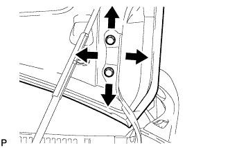
Loosen the 4 hinge bolts of the hood.
-
Adjust the clearance between the hood and front fender by moving the hood.
-
Tighten the 4 hinge bolts after the adjustment.
- Torque:
- 12 N*m { 122 kgf*cm, 9 ft.*lbf }
-
-
Adjust the height of the front end of the hood using the cushion rubbers.
-
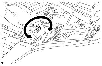
Adjust the cushion rubbers so that the heights of the hood and fender are aligned.
Tech Tips
Raise or lower the front end of the hood by turning the cushion rubbers.
-
-
Adjust the hood lock.
-
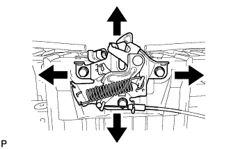
Loosen the 3 bolts.
-
Tighten the bolts after the adjustment.
- Torque:
- 7.5 N*m { 77 kgf*cm, 66 in.*lbf }
-
Check that the striker can engage with the hood lock smoothly.
-
-