POWER BACK DOOR SYSTEM Power Back Door Warning System does not Operate
DESCRIPTION
When the power back door warning system does not operate, one of the following may be malfunctioning: 1) power back door warning buzzer circuit, 2) wireless door lock control system or 3) back door motor unit (power back door ECU).
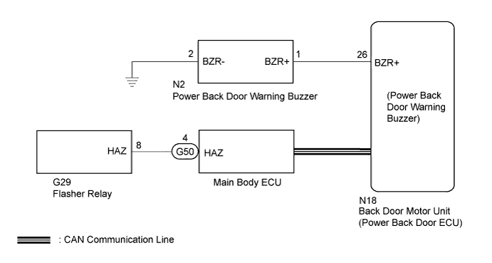
WIRING DIAGRAM
INSPECTION PROCEDURE
Note
The power back door system uses a CAN communication system. Inspect the communication function by following How to Proceed with Troubleshooting Click here. Troubleshoot the power back door system after confirming that the communication system is functioning properly.
PROCEDURE
-
CHECK OPERATION
-
Check power back door system operation.
Result Result Proceed to Power back door warning buzzer does not operate A Hazard warning light does not come on* B Power back door warning buzzer in the power back door ECU does not operate C
-
*: w/o Windshield Deicer System
-
B 
CHECK WIRELESS DOOR LOCK CONTROL SYSTEM (HAZARD ANSWER-BACK FUNCTION) Click here
C 
REPLACE BACK DOOR MOTOR UNIT (POWER BACK DOOR ECU) Click here
A 
-
-
PERFORM ACTIVE TEST ON INTELLIGENT TESTER (POWER BACK DOOR WARNING BUZZER)
-
Connect the intelligent tester to the DLC3.
-
Turn the engine switch on (IG).
-
Turn the tester on.
-
Enter the following menus: Body / Back Door / Data List.
-
Perform the Active Test, use the intelligent tester to generate a control command, and check that the power back door buzzer sounds.
Back Door (Power Back Door ECU) Tester Display Test Part Control Range Diagnostic Note PBD Buzzer Power back door buzzer sound ON / OFF - OK Buzzer sounds normally.
NG
INSPECT POWER BACK DOOR WARNING BUZZER Click here
OK 
REPLACE BACK DOOR MOTOR UNIT (POWER BACK DOOR ECU) Click here
-
-
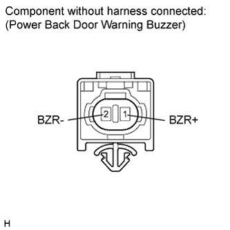
INSPECT POWER BACK DOOR WARNING BUZZER
-
Remove the power back door warning buzzer Click here.
-
Measure the resistance according to the value(s) in the table below.
Standard Resistance Tester Connection Condition Specified Condition 1 (BZR+) - 2 (BZR-) Always 950 to 1050 Ω
NG
REPLACE POWER BACK DOOR WARNING BUZZER Click here
OK
-
-
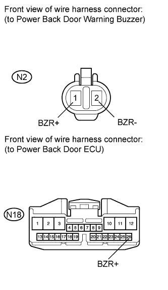
CHECK HARNESS AND CONNECTOR (POWER BACK DOOR WARNING BUZZER - POWER BACK DOOR ECU)
-
Disconnect the N18 ECU connector.
-
Disconnect the resistance according to the value(s) in the table below.
Standard Resistance Tester Connection Condition Specified Condition N2-1 (BZR+) - N18-26 (BZR+) Always Below 1 Ω N2-2 (BZR-) - Body ground Always Below 1 Ω N2-1 (BZR+) - Body ground Always 10 kΩ or higher
NG
REPAIR OR REPLACE HARNESS OR CONNECTOR
OK
REPLACE BACK DOOR MOTOR UNIT (POWER BACK DOOR ECU) Click here
-
-
CHECK WIRELESS DOOR LOCK CONTROL SYSTEM (HAZARD ANSWER-BACK FUNCTION)
-
Check wireless door lock operation.
Result Result Proceed to Hazard answer-back function operates normally A Hazard answer-back function does not operate B
B
GO TO WIRELESS DOOR LOCK CONTROL SYSTEM (NO ANSWER-BACK) Click here
A
-
-
REPLACE BACK DOOR MOTOR UNIT (POWER BACK DOOR ECU)
-
Replace the back door motor unit (power back door ECU) Click here.
NEXT
-
-
CHECK POWER BACK DOOR OPERATION
-
Check that the power back door hazard warning lights operate normally Click here.
OK The power back door hazard warning lights operate normally.
NG
REPLACE MAIN BODY ECU Click here
OK
END (BACK DOOR MOTOR UNIT (POWER BACK DOOR ECU) IS DEFECTIVE)
-