BACK DOOR CLOSER SYSTEM TERMINALS OF ECU

-
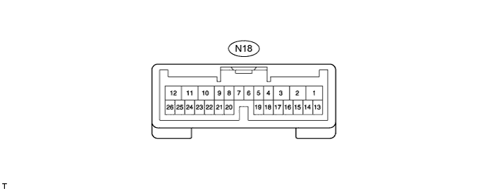
CHECK BACK DOOR MOTOR UNIT (POWER BACK DOOR ECU) (w/ Power Back Door System)
-
Disconnect the N18 power back door ECU connector.
-
Measure the voltage and resistance according to the value(s) in the table below.
Tester Connection Wiring Color Terminal Description Condition Specified Condition N18-12 (B) - Body ground B - Body ground Battery power supply Always 11 to 14 V N18-10 (ECUB) - Body ground R - Body ground Battery power supply Always 11 to 14 V N18-8 (IG) - Body ground R - Body ground IG power supply Engine switch on (IG) 11 to 14 V N18-8 (IG) - Body ground R - Body ground IG power supply Engine switch off Below 1 V N18-11 (GND) - Body ground W-B - Body ground Ground Always Below 1 Ω If the result is not as specified, there may be a malfunction in the wire harness.
-
Reconnect the N18 power back door ECU connector.
-
Initialize the power back door system Click here.
-
Measure the voltage according to the value(s) in the table below.
Tester Connection Wiring Color Terminal Description Condition Specified Condition N18-2 (DC+) - N18-1 (DC-) B - R Back door lock motor circuit Back door lock motor operating 11 to 14 V N18-2 (DC+) - N18-1 (DC-) B - R Back door lock motor circuit Back door lock motor not operating Below 1 V N18-20 (FUL) - Body ground W - Body ground Back door courtesy switch circuit Back door closed 11 to 14 V N18-20 (FUL) - Body ground W - Body ground Back door courtesy switch circuit Back door open Below 1 V N18-22 (HAF) - Body ground GR - Body ground Back door lock half-latch switch signal circuit Back door open → Back door closer operates → Back door closed Below 1 V → 11 to 14 V → Below 1 V N18-24 (POS) - Body ground P - Body ground Back door lock position switch signal circuit Back door open → Back door closer operates → Back door closed Below 1 V → 11 to 14 V → Below 1 V If the result is not as specified, the ECU may have a malfunction.
-
-
CHECK MULTIPLEX NETWORK DOOR ECU (BACK DOOR CLOSER ECU) (w/o Power Back Door System)

-
Disconnect the N33 back door closer ECU connector.
-
Measure the voltage and resistance according to the value(s) in the table below.
Tester Connection Wiring Color Terminal Description Condition Specified Condition N33-4 (B) - Body ground B - Body ground Battery power supply Always 11 to 14 V N33-16 (ECUB) - Body ground R - Body ground Battery power supply Always 11 to 14 V N33-15 (IG) - Body ground R - Body ground IG power supply Engine switch on (IG) 11 to 14 V N33-15 (IG) - Body ground R - Body ground IG power supply Engine switch off Below 1 V N33-3 (GND) - Body ground W-B - Body ground Ground Always Below 1 Ω If the result is not as specified, there may be a malfunction in the wire harness.
-
Reconnect the N33 back door closer ECU connector.
-
Measure the voltage according to the value(s) in the table below.
Tester Connection Wiring Color Terminal Description Condition Specified Condition N33-2 (DC+) - N33-1 (DC-) B - R Back door lock motor circuit Back door lock motor operating 11 to 14 V N33-2 (DC+) - N33-1 (DC-) B - R Back door lock motor circuit Back door lock motor not operating Below 1 V N33-6 (FUL) - Body ground W - Body ground Back door courtesy switch circuit Back door closed 11 to 14 V N33-6 (FUL) - Body ground W - Body ground Back door courtesy switch circuit Back door open Below 1 V N33-5 (HAF) - Body ground GR - Body ground Back door lock half-latch switch signal circuit Back door open → Back door closer operates → Back door closed Below 1 V → 11 to 14 V → Below 1 V N33-7 (POS) - Body ground P - Body ground Back door lock position switch signal circuit Back door open → Back door closer operates → Back door closed Below 1 V → 11 to 14 V → Below 1 V If the result is not as specified, the ECU may have a malfunction.
-
-
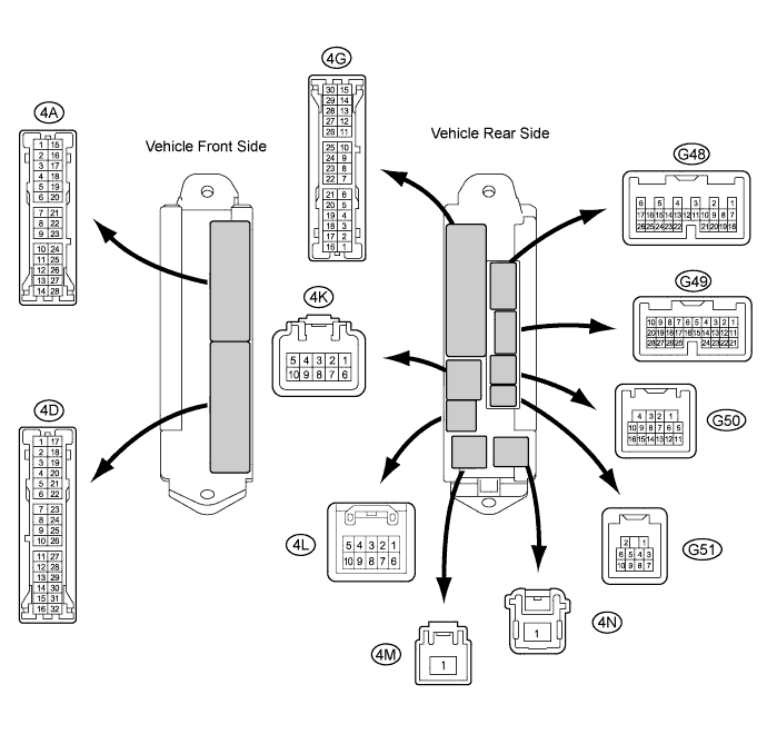
CHECK MAIN BODY ECU
-
Disconnect the G48, G49 and G50 connectors.
-
Measure the voltage and resistance according to the value(s) in the table below.
Tester Connection Wiring Color Terminal Description Condition Specified Condition G48-6 (AM1) - Body ground G - Body ground Battery power supply Always 11 to 14 V G49-1 (AM2) - Body ground G - Body ground Battery power supply Always 11 to 14 V G48-26 (BDSU) - Body ground LG - Body ground Back door opener switch signal circuit Back door opener switch off 10 kΩ or higher G48-26 (BDSU) - Body ground LG - Body ground Back door opener switch signal circuit Back door opener switch on Below 1 Ω G50-1 (GND) - Body ground W-B - Body ground Ground Always Below 1 Ω G50-16 (CANP) - Body ground B - Body ground CAN Always 10 kΩ or higher G50-15 (CANN) - Body ground W - Body ground CAN Always 10 kΩ or higher If the result is not as specified, there may be a malfunction in the wire harness.
-
Reconnect the G48, G49 and G50 connectors.
-
Measure the voltage according to the value(s) in the table below.
Tester Connection Wiring Color Terminal Description Condition Specified Condition G48-26 (BDSU) - Body ground LG - Body ground Back door opener switch signal circuit Back door opener switch off Pulse generation G48-26 (BDSU) - Body ground LG - Body ground Back door opener switch signal circuit Back door opener switch on Below 1 V If the result is not as specified, the ECU may have a malfunction.
-