Click here
INSPECTION PROCEDURE
Note:
Inspect the fuses for circuits related to this system before performing the following inspection procedure.
Click here
PROCEDURE
- Click here
CHECK HARNESS OR CONNECTOR (BATTERY AND BODY GROUND)
-
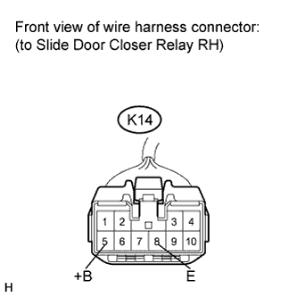
Disconnect the K14 slide door closer relay RH connector.
-
Measure the voltage according to the value(s) in the table below.
Standard Voltage Tester Connection Condition Specified Condition K14-5 (+B) - Body ground Always 11 to 14 V -
Measure the resistance according to the value(s) in the table below.
Standard Resistance Tester Connection Condition Specified Condition K14-8 (E) - Body ground Always Below 1 Ω
- OKClick here
- NGClick here
-
- Click here
REPAIR OR REPLACE HARNESS OR CONNECTOR
- Click here
PROCEED TO NEXT SUSPECTED AREA SHOWN IN PROBLEM SYMPTOMS TABLEClick here