SLIDE DOOR CLOSER SYSTEM Slide Door Closer Position Switch LH Circuit
DESCRIPTION
The switch turns on when the slide door is opened and turns off when the door is closed. Slide door position state signals are sent to the power slide door ECU.
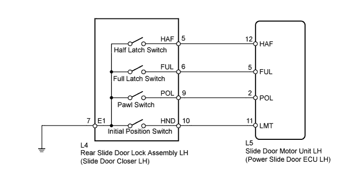
WIRING DIAGRAM
INSPECTION PROCEDURE
PROCEDURE
-
READ VALUE USING INTELLIGENT TESTER (POSITION SWITCH)
-
Connect the intelligent tester to the DLC3.
-
Turn the engine switch on (IG).
-
Enter the following menus: Body / Rear Left Door / Data List.
-
Check if the switch is functioning properly.
Rear Left Door (Power Slide Door ECU LH) Tester Display Measurement Item / Range Normal Condition Diagnosis Note Pawl Switch Status of the pawl position switch / OFF or ON OFF: Slide door fully open, closed or half latched
ON: Slide door open → half latched or slide door half latched → fully closed
- Half Switch Status of the half latch switch / OFF or ON OFF: Slide door half latched → fully closed
ON: Slide door open → half latched
- Full Switch Status of the full latch switch / OFF or ON OFF: Slide door fully closed
ON: Slide door open → fully closed
- Closer Position Switch Status of the initial position switch / OFF or ON OFF: Slide door closer motor stopped (initial position)
ON: Slide door closer motor operating
- OK When the switch is operating, the intelligent tester should display as shown in the above table.
NG 
INSPECT REAR SLIDE DOOR LOCK ASSEMBLY LH Click here
OK 
PROCEED TO NEXT SUSPECTED AREA SHOWN IN PROBLEM SYMPTOMS TABLE Click here
-
-
INSPECT REAR SLIDE DOOR LOCK ASSEMBLY LH
-
Disconnect the L4 rear slide door lock assembly connector.
-
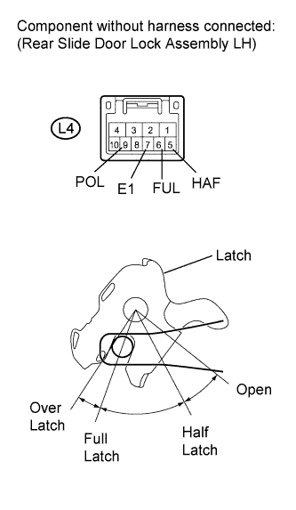
Measure the resistance according to the value(s) in the table below.
Standard Resistance Full Latch Switch Tester Connection Condition Specified Condition L4-6 (FUL) - L4-7 (E1) Open Below 1 Ω L4-6 (FUL) - L4-7 (E1) Half latch Below 1 Ω L4-6 (FUL) - L4-7 (E1) Full latch 10 kΩ or higher L4-6 (FUL) - L4-7 (E1) Over latch 10 kΩ or higher Half Latch Switch Tester Connection Condition Specified Condition L4-5 (HAF) - L4-7 (E1) Open Below 1 Ω L4-5 (HAF) - L4-7 (E1) Half latch 10 kΩ or higher L4-5 (HAF) - L4-7 (E1) Full latch 10 kΩ or higher L4-5 (HAF) - L4-7 (E1) Over latch 10 kΩ or higher Pawl Switch Tester Connection Condition Specified Condition L4-9 (POL) - L4-7 (E1) Open 10 kΩ or higher L4-9 (POL) - L4-7 (E1) Between open and half latch 10 kΩ or higher → Below 1 Ω L4-9 (POL) - L4-7 (E1) Half latch 10 kΩ or higher L4-9 (POL) - L4-7 (E1) Between half latch and full latch 10 kΩ or higher → Below 1 Ω L4-9 (POL) - L4-7 (E1) Full latch 10 kΩ or higher L4-9 (POL) - L4-7 (E1) Over latch 10 kΩ or higher -
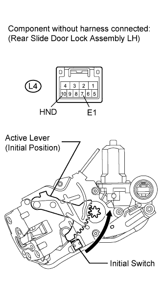
Measure the resistance according to the value(s) in the table below.
Standard Resistance Initial Switch Tester Connection Condition Specified Condition L4-10 (HND) - L4-7 (E1) Initial position 10 kΩ or higher L4-10 (HND) - L4-7 (E1) Other than initial position Below 1 Ω
NG 
REPLACE REAR SLIDE DOOR LOCK ASSEMBLY LH Click here
OK 
-
-
CHECK NO. 2 REAR DOOR WIRE (REAR SLIDE DOOR LOCK ASSEMBLY LH - ECU LH AND BODY GROUND)
-
Disconnect the L5 power slide door ECU LH connector.
-
Measure the resistance according to the value(s) in the table below.
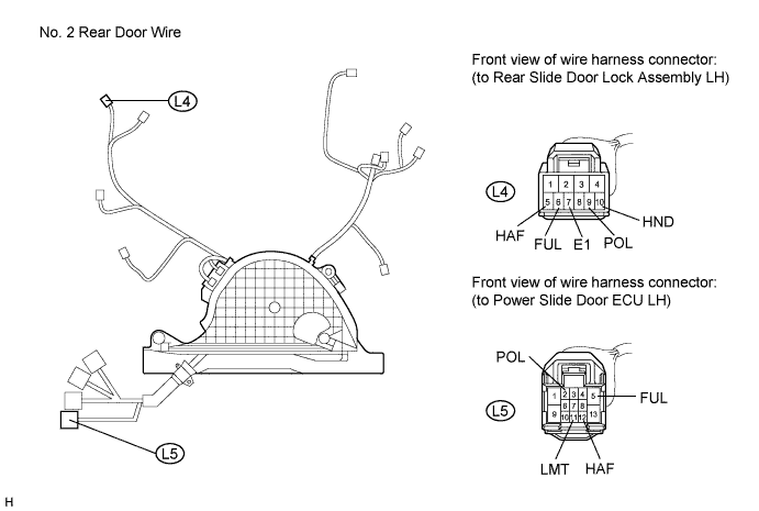
Standard Resistance Tester Connection Condition Specified Condition L4-6 (FUL) - L5-5 (FUL) Always Below 1 Ω L4-5 (HAF) - L5-12 (HAF) Always Below 1 Ω L4-9 (POL) - L5-2 (POL) Always Below 1 Ω L4-10 (HND) - L5-11 (LMT) Always Below 1 Ω L4-7 (E1) - Body ground Always Below 1 Ω L4-6 (FUL) - Body ground Always 10 kΩ or higher L4-5 (HAF) - Body ground Always 10 kΩ or higher L4-9 (POL) - Body ground Always 10 kΩ or higher L4-10 (HND) - Body ground Always 10 kΩ or higher
NG
REPAIR OR REPLACE NO. 2 REAR DOOR WIRE Click here
OK
REPLACE SLIDE DOOR MOTOR UNIT LH (POWER SLIDE DOOR ECU LH) Click here
-