SLIDE DOOR CLOSER SYSTEM Slide Door Closer Motor LH Circuit
DESCRIPTION
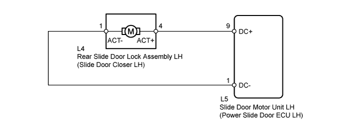
The power slide door ECU controls the slide door lock motor to open/close the slide door. This ECU applies current to terminals DC+ and DC- to operate the motor to close the door. It reverses the direction of the current to operate the motor to open the door.
WIRING DIAGRAM
INSPECTION PROCEDURE
PROCEDURE
-
INSPECT REAR SLIDE DOOR LOCK ASSEMBLY LH
-
Disconnect the L4 rear slide door lock assembly LH connector.
-
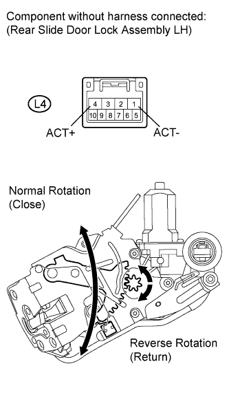
Check the operation of the slide door closer motor.
OK Tester Connection Condition Specified Condition L4-4 (ACT+) - L4-1 (ACT-) Battery voltage is applied to terminal L4-4 (ACT+) Close operation L4-4 (ACT+) - L4-1 (ACT-) Battery voltage is applied to terminal L4-1 (ACT-) Return operation
NG 
REPLACE REAR SLIDE DOOR LOCK ASSEMBLY LH Click here
OK 
-
-
CHECK NO. 2 REAR DOOR WIRE (REAR SLIDE DOOR LOCK ASSEMBLY LH - ECU LH AND BODY GROUND)
-
Disconnect the L5 power slide door ECU LH connector.
-
Measure the resistance according to the value(s) in the table below.
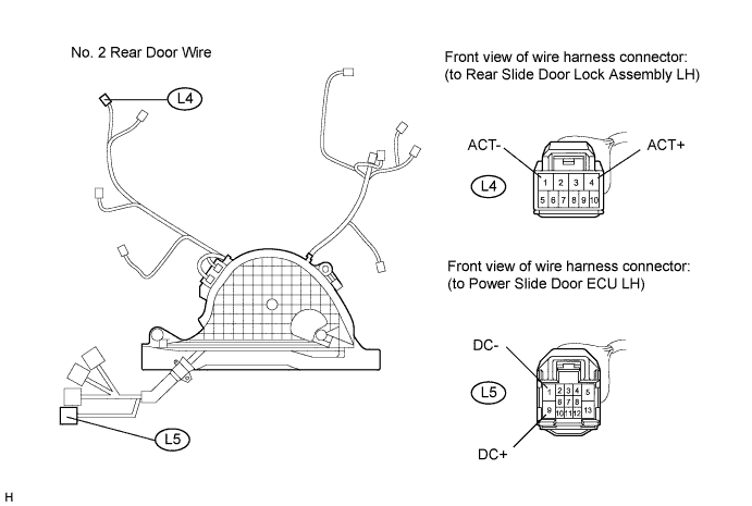
Standard Resistance Tester Connection Condition Specified Condition L4-1 (ACT-) - L5-1 (DC-) Always Below 1 Ω L4-4 (ACT+) - L5-9 (DC+) Always Below 1 Ω L4-1 (ACT-) - Body ground Always 10 kΩ or higher L4-4 (ACT+) - Body ground Always 10 kΩ or higher
NG
REPAIR OR REPLACE NO. 2 REAR DOOR WIRE Click here
OK 
PROCEED TO NEXT SUSPECTED AREA SHOWN IN PROBLEM SYMPTOMS TABLE Click here
-