SLIDE DOOR LOCK RELEASE MOTOR INSTALLATION

-
INSTALL SLIDE DOOR LOCK RELEASE MOTOR ASSEMBLY
-
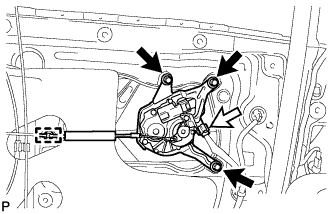
Install the slide door lock release motor assembly with the 3 screws.
-
Connect the connector.
-
Engage the clamp.
-
-
INSTALL SLIDE DOOR LOCK REMOTE CONTROL SUB-ASSEMBLY
-
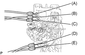
Connect each cable to the slide door lock remote control sub-assembly.
Tech Tips
Refer to the following table for the connection position of each cable:
Position Cable to be connected (A) Front lock cable (B) Rear lock cable (C) Full open stop lock cable (D) Outside handle cable (E) Release motor cable -
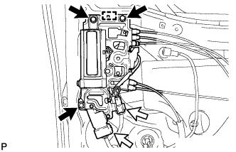
Engage the guide and install the slide door lock remote control sub-assembly.
-
Install the 3 bolts.
- Torque:
- 7.5 N*m { 77 kgf*cm, 66 in.*lbf }
-
Connect each connector.
-
-
INSTALL SLIDE DOOR WINDOW GARNISH (w/o Navigation System for HDD)
-
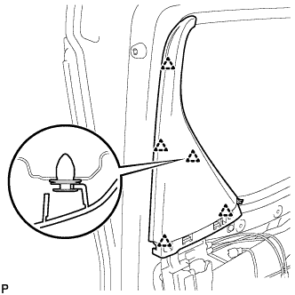
Engage the 5 clips to install the slide door window garnish.
-
-
INSTALL SLIDE DOOR WINDOW GARNISH (w/ Navigation System for HDD)
-
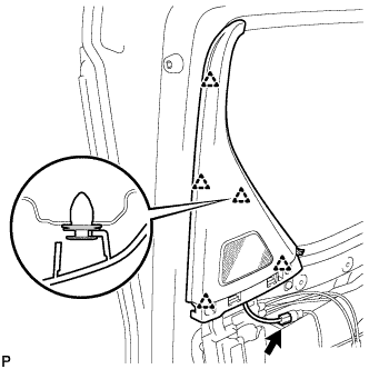
Engage the 5 clips to install the slide door window garnish.
-
Connect the connector.
-
-
INSTALL REAR DOOR TRIM BOARD SUB-ASSEMBLY
-
Connect the connector.
-
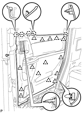
Engage the 15 clips and 5 claws to install the rear door trim board to the slide door panel.
-
Using a T25 "TORX" socket wrench, install the screw.
-