POWER SLIDE DOOR SYSTEM Power Slide Door ECU RH Power Source Circuit
DESCRIPTION
This circuit provides power to operate the slide control relay RH (ECU).
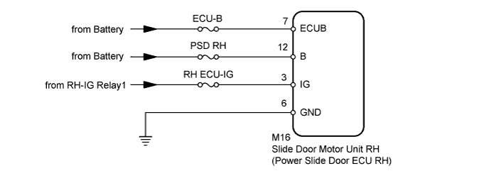
WIRING DIAGRAM
INSPECTION PROCEDURE
PROCEDURE
-
INSPECT FUSES (ECU-B, PSD RH, RH ECU-IG)
-
Remove the PSD RH and RH ECU-IG fuses from the passenger side junction block assembly.*1
-
Remove the PSD RH and RH ECU-IG fuses from the driver side junction block assembly.*2
-
*1: for LHD
-
*2: for RHD
-
-
Remove the ECU-B fuse from the no. 1 engine room relay block.
-
Measure the resistance of the fuses.
Standard Resistance Below 1 Ω
NG 
REPLACE FUSE
OK 
-
-
CHECK HARNESS AND CONNECTOR (ECU RH - BATTERY AND BODY GROUND)
-
Reinstall the PSD RH and RH ECU-IG fuses to the passenger side junction block assembly.*1
-
Reinstall the PSD RH and RH ECU-IG fuses to the driver side junction block assembly.*2
-
*1: for LHD
-
*2: for RHD
-
-
Reinstall the ECU-B fuse to the no. 1 engine room relay block.
-
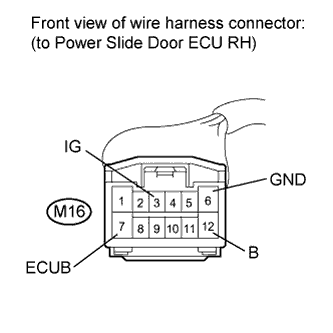
Disconnect the M16 power slide door ECU RH connector.
-
Measure the voltage according to the value(s) in the table below.
Standard Voltage Tester Connection Condition Specified Condition M16-7 (ECUB) - Body ground Always 11 to 14 V M16-3 (IG) - Body ground Engine switch on (IG) 11 to 14 V M16-12 (B) - Body ground Always 11 to 14 V -
Measure the resistance according to the value(s) in the table below.
Standard Resistance Tester Connection Condition Specified Condition M16-6 (GND) - Body ground Always Below 1 Ω
NG
REPAIR OR REPLACE HARNESS OR CONNECTOR
OK 
PROCEED TO NEXT SUSPECTED AREA SHOWN IN PROBLEM SYMPTOMS TABLE Click here
-