POWER SLIDE DOOR SYSTEM Power Slide Door ECU LH Power Source Circuit
DESCRIPTION
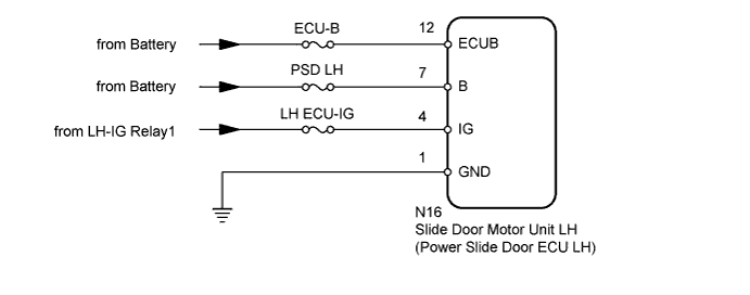
This circuit provides power to operate the slide door motor unit LH (power slide door ECU LH).
WIRING DIAGRAM
INSPECTION PROCEDURE
PROCEDURE
-
INSPECT FUSES (ECU-B, PSD LH, LH ECU-IG)
-
Remove the PSD LH and LH ECU-IG fuses from the driver side junction block assembly.*1
-
Remove the PSD LH and LH ECU-IG fuses from the passenger side junction block assembly.*2
-
*1: for LHD
-
*2: for RHD
-
-
Remove the ECU-B fuse from the no. 1 engine room relay block.
-
Measure the resistance of the fuses.
Standard Resistance Below 1 Ω
NG 
REPLACE FUSE
OK 
-
-
CHECK HARNESS AND CONNECTOR (ECU LH - BATTERY AND BODY GROUND)
-
Reinstall the PSD LH and LH ECU-IG fuses to the driver side junction block assembly.*1
-
Reinstall the PSD LH and LH ECU-IG fuses to the passenger side junction block assembly.*2
-
*1: for LHD
-
*2: for RHD
-
-
Reinstall the ECU-B fuse to the no. 1 engine room relay block.
-
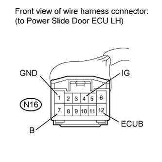
Disconnect the N16 power slide door ECU LH connector.
-
Measure the voltage according to the value(s) in the table below.
Standard Voltage Tester Connection Condition Specified Condition N16-12 (ECUB) - Body ground Always 11 to 14 V N16-4 (IG) - Body ground Engine switch on (IG) 11 to 14 V N16-7 (B) - Body ground Always 11 to 14 V -
Measure the resistance according to the value(s) in the table below.
Standard Resistance Tester Connection Condition Specified Condition N16-1 (GND) - Body ground Always Below 1 Ω
NG
REPAIR OR REPLACE HARNESS OR CONNECTOR
OK 
PROCEED TO NEXT SUSPECTED AREA SHOWN IN PROBLEM SYMPTOMS TABLE Click here
-