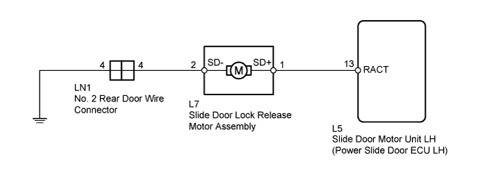
POWER SLIDE DOOR SYSTEM Slide Door Lock Release Motor LH Circuit
DESCRIPTION
The slide door lock release motor assembly unlocks the power slide door lock and unlock position switch when the power slide door is operated by the transmitter or power slide door control switch with the slide door closed.
WIRING DIAGRAM
INSPECTION PROCEDURE
PROCEDURE
-
INSPECT SLIDE DOOR LOCK RELEASE MOTOR ASSEMBLY
-
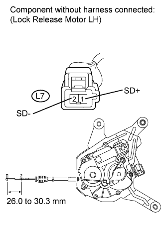
Remove the slide door lock release motor assembly Click here.
-
Apply battery voltage to the motor terminals and check the operation of the slide door lock release motor assembly.
OK Tester Connection Condition Specified Condition L7-1 (SD+) - L7-2 (SD-) Battery voltage is applied to terminal 1 (SD+) Lock released Standard Stroke 26.0 to 30.3 mm (1.02 to 1.19 in.)
NG 
REPLACE SLIDE DOOR LOCK RELEASE MOTOR ASSEMBLY Click here
OK 
-
-
CHECK NO. 2 REAR DOOR WIRE (LOCK RELEASE MOTOR - ECU LH)
-
Disconnect the L5 power slide door ECU LH connector.
-
Measure the resistance according to the value(s) in the table below.
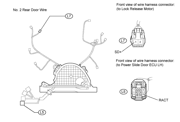
Standard Resistance Tester Connection Condition Specified Condition L7-1 (SD+) - L5-13 (RACT) Always Below 1 Ω L7-1 (SD+) - Body ground Always 10 kΩ or higher
NG
REPAIR OR REPLACE NO. 2 REAR DOOR WIRE Click here
OK
-
-
CHECK NO. 2 REAR DOOR WIRE (LOCK RELEASE MOTOR - BODY GROUND)
-
Disconnect the LN1 No. 2 rear door wire connector.
-
Measure the resistance according to the value(s) in the table below.
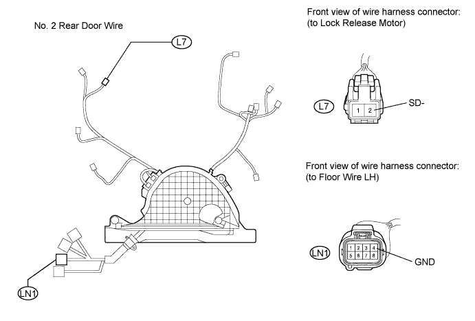
Standard Resistance Tester Connection Condition Specified Condition L7-2 (SD-) - LN1-4 (GND) Always Below 1 Ω
NG
REPAIR OR REPLACE NO. 2 REAR DOOR WIRE Click here
OK
-
-
CHECK HARNESS AND CONNECTOR (BODY GROUND)
-
Measure the resistance according to the value(s) in the table below.
Standard Resistance Tester Connection Condition Specified Condition LN1-4 (GND) - Body ground Always Below 1 Ω
NG
REPAIR OR REPLACE HARNESS OR CONNECTOR
OK 
PROCEED TO NEXT SUSPECTED AREA SHOWN IN PROBLEM SYMPTOMS TABLE Click here
-