POWER SLIDE DOOR SYSTEM, Diagnostic DTC:B2224

| DTC Code | DTC Name |
|---|---|
| B2224 | Power Slide Door Pulse Sensor Malfunction on Rear Left Door |
DESCRIPTION
-
A pulse sensor is built into the slide door LH for jam and foreign matter detection and for slide door position detection. The pulse sensor monitors the operating speed of the slide door while the power slide door is moving. The pulse sensor monitors where the slide door is. If the pulse signal is out of the normal range, the power slide door ECU LH will store DTC B2224.
-
If DTC B2224 is stored, the power slide door system will be turned off. Thus, the slide door can be moved freely and will be switched to manual operation mode (not electrically controlled).
-
In order to restore the power slide door system to normal operation mode, first repair the malfunction indicated by DTC B2224 and then manually close the slide door fully (reset operation).
| DTC No. | DTC Detection Condition | Trouble Area |
|---|---|---|
| B2224 | A pulse sensor which is built in the slide door motor unit LH (power slide door ECU LH) is malfunction. |
|
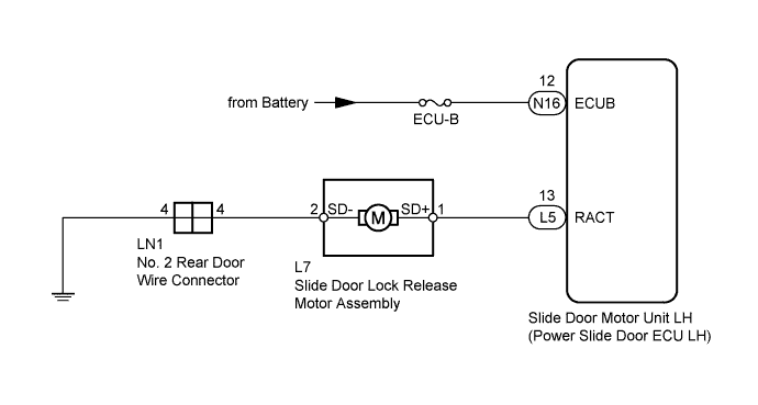
WIRING DIAGRAM
INSPECTION PROCEDURE
Note
Inspect the fuses for circuits related to this system before performing the following inspection procedure.
PROCEDURE
-
CHECK HARNESS AND CONNECTOR (ECU LH - BATTERY)
-
Disconnect the N16 power slide door ECU LH connector.
-
Measure the voltage according to the value(s) in the table below.
Standard Voltage Tester Connection Condition Specified Condition N16-12 (ECUB) - Body ground Always 11 to 14 V
NG 
REPAIR OR REPLACE HARNESS OR CONNECTOR
OK 
-
-
INSPECT SLIDE DOOR LOCK RELEASE MOTOR ASSEMBLY
-
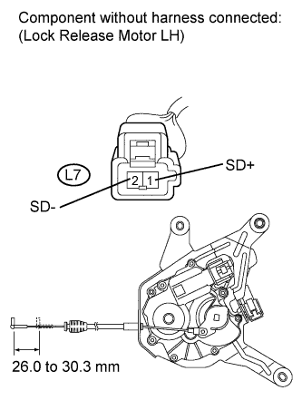
Remove the slide door lock release motor assembly Click here.
-
Apply battery voltage to the motor terminals and check the operation of the slide door lock release motor assembly.
OK Tester Connection Condition Specified Condition L7-1 (SD+) - L7-2 (SD-) Battery voltage is applied to terminal 1 (SD+) Lock released Standard Stroke 26.0 to 30.3 mm (1.02 to 1.19 in.)
NG
REPLACE SLIDE DOOR LOCK RELEASE MOTOR ASSEMBLY Click here
OK
-
-
CHECK NO. 2 REAR DOOR WIRE (LOCK RELEASE MOTOR - ECU LH)
-
Disconnect the L5 power slide door ECU LH connector.
-
Measure the resistance according to the value(s) in the table below.
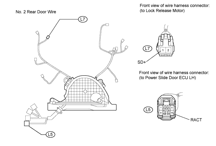
Standard Resistance Tester Connection Condition Specified Condition L7-1 (SD+) - L5-13 (RACT) Always Below 1 Ω L7-1 (SD+) - Body ground Always 10 kΩ or higher
NG
REPAIR OR REPLACE NO. 2 REAR DOOR WIRE Click here
OK
-
-
CHECK NO. 2 REAR DOOR WIRE (LOCK RELEASE MOTOR - BODY GROUND)
-
Disconnect the LN1 No. 2 rear door wire connector.
-
Measure the resistance according to the value(s) in the table below.
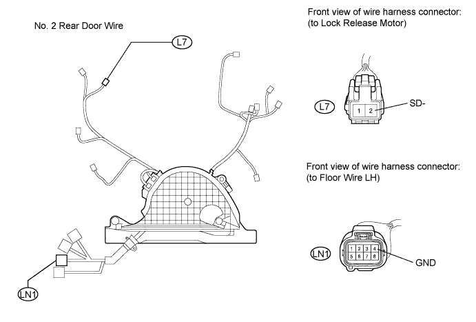
Standard Resistance Tester Connection Condition Specified Condition L7-2 (SD-) - LN1-4 (GND) Always Below 1 Ω
NG
REPAIR OR REPLACE NO. 2 REAR DOOR WIRE Click here
OK
-
-
CHECK HARNESS AND CONNECTOR (BODY GROUND)
-
Measure the resistance according to the value(s) in the table below.
Standard Resistance Tester Connection Condition Specified Condition LN1-4 (GND) - Body ground Always Below 1 Ω
NG
REPAIR OR REPLACE HARNESS OR CONNECTOR
OK 
REPLACE SLIDE DOOR MOTOR UNIT LH Click here
-