Click here
-
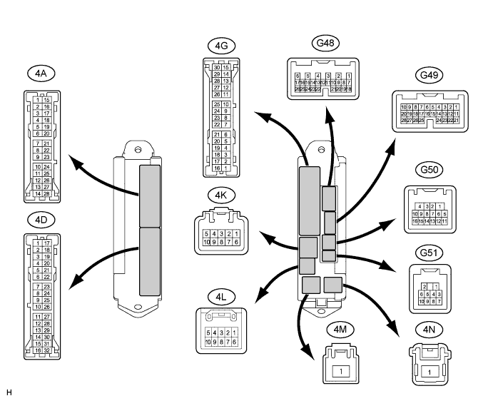
CHECK MAIN BODY ECU
-
Disconnect the G51, G50, G49, G48 and 4D connectors from the main body ECU.
-
Measure the voltage and resistance according to the value(s) in the table below.
Tester Connection Wiring Color Terminal Description Condition Specified Condition G48-6 (AM1) - Body ground G - Body ground Battery power supply Always 11 to 14 V G49-1 (AM2) - Body ground G - Body ground Battery power supply Always 11 to 14 V G50-1 (GND) - Body ground W-B - Body ground Ground Always Below 1 V 4D-6 (LSWL) - Body ground SB - Body ground Slide door LH lock position switch input Slide door LH LOCK → UNLOCK 10 kΩ or higher → Below 1 Ω G49-5 (LSWR) - Body ground*1 Y - Body ground Slide door RH lock position switch input Slide door RH LOCK → UNLOCK 10 kΩ or higher → Below 1 Ω G51-8 (RLSD) - Body ground L - Body ground Power slide door control switch LH input Power slide door control switch LH OFF → ON 10 kΩ or higher → Below 1 Ω G50-7 (RRSD) - Body ground*1 P - Body ground Power slide door control switch RH input Power slide door control switch RH OFF → ON 10 kΩ or higher → Below 1 Ω G50-16 (CANP) - Body ground B - Body ground CAN Always 10 kΩ or higher G50-15 (CANN) - Body ground W - Body ground CAN Always 10 kΩ or higher *1: w/ Power Slide Door RH
-
Reconnect the G51, G50, G49, G48 and 4D connectors to the main body ECU.
-
Measure the voltage according to the value(s) in the table below.
Tester Connection Wiring Color Terminal Description Condition Specified Condition 4D-6 (LSWL) - G50-1 (GND) SB - W-B Slide door LH lock position switch input Slide door LH LOCK → UNLOCK Pulse generation → Below 1 V
(Reference)
G49-5 (LSWR) - G50-1 (GND)*1 Y - W-B Slide door RH lock position switch input Slide door RH LOCK → UNLOCK Pulse generation → Below 1 V
(Reference)
G51-8 (RLSD) - G50-1 (GND) L - W-B Power slide door control switch LH input Power slide door control switch LH OFF → ON Pulse generation (See waveform 1) → Below 1 V G50-7 (RRSD) - G50-1 (GND)*1 P - W-B Power slide door control switch RH input Power slide door control switch RH OFF → ON Pulse generation (See waveform 1) → Below 1 V *1: w/ Power Slide Door RH
-
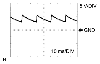
Waveform 1 (power slide door control switch signal)
Terminal (Symbol) G51-8 (RLSD) - G50-1 (GND)
G50-7 (RRSD) - G50-1 (GND)*1
Tester Range 5 V/DIV, 10 ms/DIV Condition Always *1: w/ Power Slide Door RH
-
-

CHECK SLIDE DOOR MOTOR UNIT LH (POWER SLIDE DOOR ECU LH)
-
Disconnect the L5 and N16 connectors from the power slide door ECU LH.
-
Measure the voltage and resistance according to the value(s) in the table below.
Tester Connection Wiring Color Terminal Description Condition Specified Condition N16-12 (ECUB) - N16-1 (GND) R - W-B Power supply Always 11 to 14 V N16-7 (B) - N16-1 (GND) R - W-B Power supply Always 11 to 14 V N16-4 (IG) - N16-1 (GND) R - W-B Power supply Engine switch on (IG) 11 to 14 V N16-1 (GND) - Body ground W-B - Body ground Ground Always Below 1 Ω N16-8 (MSW) - N16-1 (GND) B - W-B Main switch input Power slide door main switch off and fuel lid closed Below 1 Ω Power slide door main switch on or fuel lid open 10 kΩ or higher L5-2 (POL) - N16-1 (GND) G - W-B PAWL switch input Slide door fully closed → half latched (latch pushed slightly toward full latch position) 10 kΩ or higher → Below 1 Ω → 10 kΩ or higher Half latched Below 1 Ω Slide door fully open → half latched (latch pushed slightly toward full latch position) 10 kΩ or higher → Below 1 Ω → 10 kΩ or higher L5-5 (FUL) - N16-1 (GND) BR - W-B Full latch switch input Slide door open → fully closed Below 1 Ω → 10 kΩ or higher L5-12 (HAF) - N16-1 (GND) P - W-B Half latch switch input Slide door fully open → half latched Below 1 Ω → 10 kΩ or higher L5-7 (DS2) - N16-1 (GND) LG - W-B Handle switch input Handle not operated 10 kΩ or higher Outside handle pulled or inside handle turned to close Below 1 Ω L5-10 (DS1) - N16-1 (GND) L - W-B Handle switch input Handle not operated 10 kΩ or higher Outside handle pulled or inside handle turned to open Below 1 Ω L5-8 (OS) - L5-4 (OSG) GR - W Touch switch input Power slide door touch sensor pushed Below 100 Ω Power slide door touch sensor not pushed Between 500 Ω and 1100 Ω N16-11 (MPX1) - Body ground B - Body ground CAN Always 10 kΩ or higher N16-5 (MPX2) - Body ground W - Body ground CAN Always 10 kΩ or higher -
Reconnect the L5 and N16 connectors to the power slide door ECU LH.
-
Measure the voltage according to the value(s) in the table below.
Tester Connection Wiring Color Terminal Description Condition Specified Condition L5-1 (DC-) - N16-1 (GND) G - W-B Door closer output (Reverse rotation) Slide door open Below 1 V Half latched Below 1 V Normal rotation Below 1 V Reverse rotation 11 to 14 V Operation finished Below 1 V L5-9 (DC+) - N16-1 (GND) L - W-B Door closer output (Normal rotation) Slide door open Below 1 V Half latched Below 1 V Normal rotation 11 to 14 V Reverse rotation Below 1 V Operation finished Below 1 V L5-11 (LMT) - N16-1 (GND) B - W-B Initial position switch input Slide door open Below 1 V Half latched Below 1 V Normal rotation Below 1 V Reverse rotation Below 1 V Operation finished 11 to 14 V L5-13 (RACT) - N16-1 (GND) R - W-B Latch release output Slide door fully closed and power slide door control switch operated or power slide door control switch on (wireless operation) 11 to 14 V Slide door closing Below 1 V Slide door fully open Below 1 V
-
-

CHECK SLIDE DOOR MOTOR UNIT RH (POWER SLIDE DOOR ECU RH) (w/ Power Slide Door RH)
-
Disconnect the K5 and M16 connectors from the power slide door ECU RH.
-
Measure the voltage and resistance according to the value(s) in the table below.
Tester Connection Wiring Color Terminal Description Condition Specified Condition M16-7 (ECUB) - M16-6 (GND) LG - W-B Power supply Always 11 to 14 V M16-12 (B) - M16-6 (GND) R - W-B Power supply Always 11 to 14 V M16-3 (IG) - M16-6 (GND) R - W-B Power supply Engine switch on (IG) 11 to 14 V M16-6 (GND) - Body ground W-B - Body ground Ground Always Below 1 Ω M16-11 (MSW) - M16-6 (GND) LG - W-B Main switch input Power slide door main switch off Below 1 Ω Power slide door main switch on 10 kΩ or higher K5-4 (POL) - M16-6 (GND) G - W-B PAWL switch input Slide door fully closed → half latched (latch pushed slightly toward full latch position) 10 kΩ or higher → Below 1 Ω → 10 kΩ or higher Half latched Below 1 Ω Slide door fully open → half latched (latch pushed slightly toward full latch position) 10 kΩ or higher → Below 1 Ω → 10 kΩ or higher K5-1 (FUL) - M16-6 (GND) BR - W-B Full latch switch input Slide door open → fully closed Below 1 Ω → 10 kΩ or higher K5-10 (HAF) - M16-6 (GND) P - W-B Half latch switch input Slide door fully open → half latched Below 1 Ω → 10 kΩ or higher K5-7 (DS2) - M16-6 (GND) LG - W-B Handle switch input Handle not operated 10 kΩ or higher Outside handle pulled or inside handle turned to close Below 1 Ω K5-12 (DS1) - M16-6 (GND) L - W-B Handle switch input Handle not operated 10 kΩ or higher Outside handle pulled or inside handle turned to open Below 1 Ω K5-6 (OS) - K5-2 (OSG) GR - W Touch switch input Power slide door touch sensor pushed Below 100 Ω Power slide door touch sensor not pushed Between 500 Ω and 1100 Ω M16-8 (MPX1) - Body ground R - Body ground CAN Always 10 kΩ or higher M16-2 (MPX2) - Body ground W - Body ground CAN Always 10 kΩ or higher -
Reconnect the K5 and M16 connectors to the power slide door ECU RH.
-
Measure the voltage according to the value(s) in the table below.
Tester Connection Wiring Color Terminal Description Condition Specified Condition K5-5 (DC-) - M16-6 (GND) G - W-B Door closer output (Reverse rotation) Slide door open Below 1 V Half latched Below 1 V Normal rotation Below 1 V Reverse rotation 11 to 14 V Operation finished Below 1 V K5-13 (DC+) - M16-6 (GND) L - W-B Door closer output (Normal rotation) Slide door open Below 1 V Half latched Below 1 V Normal rotation 11 to 14 V Reverse rotation Below 1 V Operation finished Below 1 V K5-11 (LMT) - M16-6 (GND) B - W-B Initial position switch input Slide door open Below 1 V Half latched Below 1 V Normal rotation Below 1 V Reverse rotation Below 1 V Operation finished 11 to 14 V K5-9 (RACT) - M16-6 (GND) R - W-B Latch release output Slide door fully closed and power slide door control switch operated or power slide door control switch on (wireless operation) 11 to 14 V Slide door closing Below 1 V Slide door fully open Below 1 V
-