SLIDING ROOF SYSTEM Sliding Roof does not Move by Operating Sliding Roof Control Switch
DESCRIPTION
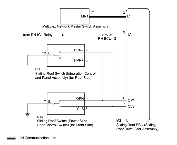
The sliding roof ECU (sliding roof drive gear assembly) receives sliding roof switch signals and drives its built-in motor.
WIRING DIAGRAM
INSPECTION PROCEDURE
Note
-
When the sliding roof ECU (sliding roof drive gear assembly) is replaced or removed and reinstalled, it requires initialization Click here.
-
The sliding roof system uses LIN communication. First, confirm that there is no malfunction in the communication system by checking communication function of the LIN communication system. Refer to the How to Proceed with Troubleshooting procedure Click here.
PROCEDURE
-
CHECK POWER WINDOW CONTROL SYSTEM (REMOTE UP/DOWN FUNCTION)
-
Check that the each door power windows move when the remote up/down function of the multiplex network master switch assembly is operated Click here.
OK Each door power windows up/down function is normal.
NG 
GO TO POWER WINDOW CONTROL SYSTEM Click here
OK 
-
-
INSPECT FUSE (RH ECU-IG)
-
Remove the RH ECU-IG fuse from the driver side junction block*1 or passenger side junction block*2.
-
*1: for LHD
-
*2: for RHD
-
-
Measure the resistance according to the value(s) in the table below.
Standard Resistance Tester Connection Condition Specified Condition RH ECU-IG fuse Always Below 1 Ω
NG
REPLACE FUSE (RH ECU-IG)
OK
-
-
CHECK HARNESS AND CONNECTOR (SLIDING ROOF ECU - BATTERY)
-
Install the RH ECU-IG fuse to the driver side junction block*1 or passenger side junction block*2.
-
*1: for LHD
-
*2: for RHD
-
-
Disconnect the M2 ECU connector.
-
Measure the voltage according to the value(s) in the table below.
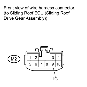
Standard Voltage Tester Connection Condition Specified Condition M2-9 (IG) - Body ground Engine switch on (IG) 11 to 14 V M2-9 (IG) - Body ground Engine switch off Below 1 V
NG
REPAIR OR REPLACE HARNESS OR CONNECTOR
OK
-
-
CHECK SLIDING ROOF SYSTEM (BASIC FUNCTION)
-
Reconnect the M2 ECU connector.
-
Check the sliding roof basic function Click here.
Result Result Proceed to Sliding roof does not operate by sliding roof switch (power slide door control switch) (for front side). A Sliding roof does not operate by sliding roof switch (integration control and panel assembly) (for rear side). B Tech Tips
If the sliding roof does not operate by both front and rear side sliding roof switches, proceed to "A" first.
B 
CHECK HARNESS AND CONNECTOR (SLIDING ROOF ECU - SLIDING ROOF SWITCH) Click here
A
-
-
CHECK HARNESS AND CONNECTOR (SLIDING ROOF ECU - SLIDING ROOF SWITCH)
-
Disconnect the M2 ECU connector.
-
Disconnect the R14 switch connector.
-
Measure the resistance according to the value(s) in the table below.
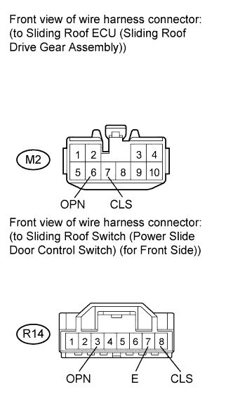
Standard Resistance Tester Connection Condition Specified Condition M2-6 (OPN) - R14-3 (OPN) Always Below 1 Ω M2-7 (CLS) - R14-8 (CLS) Always Below 1 Ω R14-7 (E) - Body ground Always Below 1 Ω R14-3 (OPN) - Body ground Always 10 kΩ or higher R14-8 (CLS) - Body ground Always 10 kΩ or higher
NG
REPAIR OR REPLACE HARNESS OR CONNECTOR
OK
-
-
INSPECT SLIDING ROOF SWITCH (POWER SLIDE DOOR CONTROL SWITCH) (for Front Side)
-
Remove the sliding roof switch (power slide door control switch) (for front side) Click here.
-
Measure the resistance according to the value(s) in the table below.
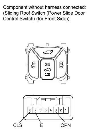
Standard Resistance Tester Connection Switch Condition Specified Condition 3 (OPN) - 7 (E) Front sliding roof switch OPEN Below 1 Ω 3 (OPN) - 7 (E)
8 (CLS) - 7 (E)
Front sliding roof switch off 10 kΩ or higher 8 (CLS) - 7 (E) Front sliding roof switch CLOSE Below 1 Ω
NG
REPLACE SLIDING ROOF SWITCH (POWER SLIDE DOOR CONTROL SWITCH) (for Front Side) Click here
OK 
REPLACE SLIDING ROOF ECU (SLIDING ROOF DRIVE GEAR ASSEMBLY) Click here
-
-
CHECK HARNESS AND CONNECTOR (SLIDING ROOF ECU - SLIDING ROOF SWITCH)
-
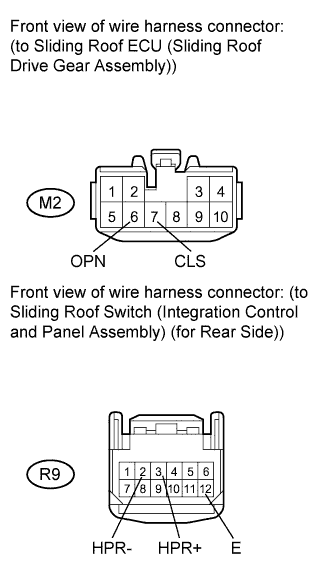
Disconnect the M2 ECU connector.
-
Disconnect the R9 switch connector.
-
Measure the resistance according to the value(s) in the table below.
Standard Resistance Tester Connection Condition Specified Condition M2-6 (OPN) - R9-3 (HPR+) Always Below 1 Ω M2-7 (CLS) - R9-2 (HPR-) Always Below 1 Ω R9-12 (E) - Body ground Always Below 1 Ω R9-2 (HPR-) - Body ground Always 10 kΩ or higher R9-3 (HPR+) - Body ground Always 10 kΩ or higher
NG
REPAIR OR REPLACE HARNESS OR CONNECTOR
OK
-
-
INSPECT SLIDING ROOF SWITCH (INTEGRATION CONTROL AND PANEL ASSEMBLY) (for Rear Side)
-
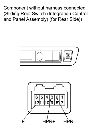
Remove the sliding roof switch (integration control and panel assembly) (for rear side) Click here.
-
Measure the resistance according to the value(s) in the table below.
Standard Resistance Tester Connection Switch Condition Specified Condition 2 (HPR-) - 12 (E) Rear sliding roof switch CLOSE Below 1 Ω 2 (HPR-) - 12 (E)
3 (HPR+) - 12 (E)
Rear sliding roof switch off 10 kΩ or higher 3 (HPR+) - 12 (E) Rear sliding roof switch OPEN Below 1 Ω
NG
REPLACE SLIDING ROOF SWITCH (INTEGRATION CONTROL AND PANEL ASSEMBLY) (for Rear Side) Click here
OK
REPLACE SLIDING ROOF ECU (SLIDING ROOF DRIVE GEAR ASSEMBLY) Click here
-