SLIDING ROOF SYSTEM, Diagnostic DTC:B2341, B2344

| DTC Code | DTC Name |
|---|---|
| B2341 | Sensor (Motor) Failure |
| B2344 | Position Failure |
DESCRIPTION
When the sliding roof ECU (sliding roof drive gear assembly) detects a motor malfunction and the sliding roof operation is stopped, DTC B2341 is output.
When the sliding roof ECU (sliding roof drive gear assembly) detects a gear malfunction and the sliding roof operation is stopped, DTC B2344 is output.
| DTC Code | DTC Detection Condition | Trouble Area |
|---|---|---|
| B2341 | Sensor (motor) failure (When the ECU enters fail-safe mode due to a problem with the motor) |
|
| B2344 | Position failure (When the ECU enters fail-safe mode due to a problem with the gear position) |
|
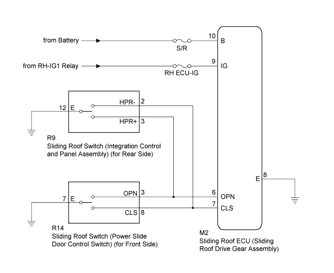
WIRING DIAGRAM
INSPECTION PROCEDURE
Note
When the sliding roof ECU (sliding roof drive gear assembly) is replaced or removed and reinstalled, it requires initialization Click here.
PROCEDURE
-
CHECK SLIDING ROOF OPERATION
-
Check the sliding roof auto operation Click here.
OK Auto operation operates normally.
NG 
INITIALIZE SLIDING ROOF ECU (SLIDING ROOF DRIVE GEAR ASSEMBLY) Click here
OK 
-
-
CHECK DTC OUTPUT
-
Clear the DTC Click here.
-
Recheck for DTCs.
OK DTC B2341 or B2344 is not output.
NG 
REPLACE SLIDING ROOF ECU (SLIDING ROOF DRIVE GEAR ASSEMBLY) Click here
OK 
USE SIMULATION METHOD TO CHECK Click here
-
-
INITIALIZE SLIDING ROOF ECU (SLIDING ROOF DRIVE GEAR ASSEMBLY)
-
Check that the sliding roof ECU (sliding roof drive gear assembly) can be initialized Click here.
OK Sliding roof ECU (sliding roof drive gear assembly) can be initialized.
NG
CHECK HARNESS AND CONNECTOR (SLIDING ROOF ECU - SLIDING ROOF SWITCH) Click here
OK
-
-
CHECK DTC OUTPUT
-
Clear the DTC Click here.
-
Recheck for DTCs.
OK DTC B2341 or B2344 is not output.
NG
REPLACE SLIDING ROOF ECU (SLIDING ROOF DRIVE GEAR ASSEMBLY) Click here
OK
END
-
-
CHECK HARNESS AND CONNECTOR (SLIDING ROOF ECU - SLIDING ROOF SWITCH)
-
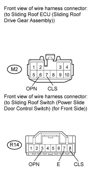
Disconnect the R14 switch connector.
-
Disconnect the M2 ECU connector.
-
Measure the resistance according to the value(s) in the table below.
Standard Resistance Tester Connection Condition Specified Condition M2-6 (OPN) - R14-3 (OPN) Always Below 1 Ω M2-7 (CLS) - R14-8 (CLS) Always Below 1 Ω R14-7 (E) - Body ground Always Below 1 Ω R14-3 (OPN) - Body ground Always 10 kΩ or higher R14-8 (CLS) - Body ground Always 10 kΩ or higher
NG
REPAIR OR REPLACE HARNESS OR CONNECTOR
OK
-
-
INSPECT SLIDING ROOF SWITCH (POWER SLIDE DOOR CONTROL SWITCH) (for Front Side)
-
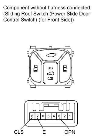
Remove the sliding roof switch (power slide door control switch) (for front side) Click here.
-
Measure the resistance according to the value(s) in the table below.
Standard Resistance Tester Connection Switch Condition Specified Condition 3 (OPN) - 7 (E) Front sliding roof switch OPEN Below 1 Ω 3 (OPN) - 7 (E)
8 (CLS) - 7 (E)
Front sliding roof switch off 10 kΩ or higher 8 (CLS) - 7 (E) Front sliding roof switch CLOSE Below 1 Ω
NG
REPLACE SLIDING ROOF SWITCH (POWER SLIDE DOOR CONTROL SWITCH) (for Front Side) Click here
OK
-
-
CHECK HARNESS AND CONNECTOR (SLIDING ROOF ECU - SLIDING ROOF SWITCH)
-
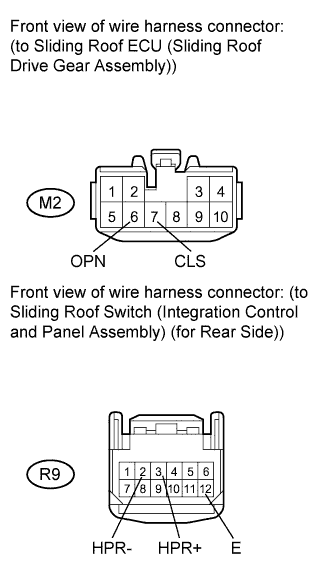
Disconnect the R9 switch connector.
-
Disconnect the M2 ECU connector.
-
Measure the resistance according to the value(s) in the table below.
Standard Resistance Tester Connection Condition Specified Condition M2-6 (OPN) - R9-3 (HPR+) Always Below 1 Ω M2-7 (CLS) - R9-2 (HPR-) Always Below 1 Ω R9-12 (E) - Body ground Always Below 1 Ω R9-2 (HPR-) - Body ground Always 10 kΩ or higher R9-3 (HPR+) - Body ground Always 10 kΩ or higher
NG
REPAIR OR REPLACE HARNESS OR CONNECTOR
OK
-
-
INSPECT SLIDING ROOF SWITCH (INTEGRATION CONTROL AND PANEL ASSEMBLY) (for Rear Side)
-
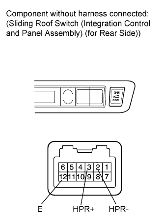
Remove the sliding roof switch (integration control and panel assembly) (for rear side) Click here.
-
Measure the resistance according to the value(s) in the table below.
Standard Resistance Tester Connection Switch Condition Specified Condition 2 (HPR-) - 12 (E) Rear sliding roof switch CLOSE Below 1 Ω 2 (HPR-) - 12 (E)
3 (HPR+) - 12 (E)
Rear sliding roof switch off 10 kΩ or higher 3 (HPR+) - 12 (E) Rear sliding roof switch OPEN Below 1 Ω
NG
REPLACE SLIDING ROOF SWITCH (INTEGRATION CONTROL AND PANEL ASSEMBLY) (for Rear Side) Click here
OK
REPLACE SLIDING ROOF ECU (SLIDING ROOF DRIVE GEAR ASSEMBLY) Click here
-