DESCRIPTION
Turning the power slide door main switch off (pushed in) prohibits power slide door control system operation.
The power slide door ECU monitors if the fuel lid is open via the fuel lid courtesy switch. When the power slide door motor is operating while the fuel lid is open, the slide door will not open fully.
INSPECTION PROCEDURE
PROCEDURE
- Click here
READ VALUE USING INTELLIGENT TESTER
-
Connect the intelligent tester to the DLC3.
-
Turn the engine switch on (IG).
-
Enter the following menus: Body / Rear Left Door / Data List.
-
Check if the switch is functioning properly.
Table 1. Rear Left Door (Power Slide Door ECU LH) Tester Display Measurement Item / Range Normal Condition Diagnosis Note PSD Main Switch Power slide door main switch signal / ON or OFF ON: Power slide door main switch not pressed and fuel lid closed
OFF: Power slide door main switch pressed or fuel lid open
- OK The intelligent tester should display as shown in the table according to switch operation. Result Result Proceed to OK (w/ Power Slide Door RH) A OK (w/o Power Slide Door RH) B NG C
-
- Click here
READ VALUE USING INTELLIGENT TESTER
-
Enter the following menus: Body / Rear Right Door / Data List.
-
Check if the switch is functioning properly.
Table 2. Rear Right Door (Power Slide Door ECU RH) Tester Display Measurement Item / Range Normal Condition Diagnosis Note PSD Main Switch Power slide door main switch signal / ON or OFF ON: Power slide door main switch not pressed
OFF: Power slide door main switch pressed
- OK The intelligent tester should display as shown in the table according to switch operation.
- OKClick here
- NGClick here
-
- Click here
INSPECT POWER SLIDE DOOR MAIN SWITCH
-
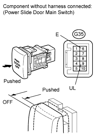
Remove the power slide door main switch on the instrument panel.
-
Measure the resistance according to the value(s) in the table below.
Standard Resistance Tester Connection Switch Condition Specified Condition G35-9 (UL) - G35-6 (E) Pushed 10 kΩ or higher G35-9 (UL) - G35-6 (E) OFF Below 1 Ω
- OKClick here
- NGClick here
-
- Click here
CHECK WIRE HARNESS AND CONNECTOR (MAIN SWITCH - POWER SLIDE DOOR ECU RH AND BODY GROUND)
-
Disconnect the M16 power slide door ECU RH connector.
-
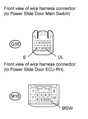
Measure the resistance according to the value(s) in the table below.
Standard Resistance Tester Connection Condition Specified Condition G35-9 (UL) - M16-11 (MSW) Always Below 1 Ω G35-9 (UL) - Body ground Always 10 kΩ or higher G35-6 (E) - Body ground Always Below 1 Ω
- OKClick here
- NGClick here
-
- Click here
INSPECT POWER SLIDE DOOR MAIN SWITCH
-
Remove the power slide door main switch on the instrument panel.
-
Measure the resistance according to the value(s) in the table below.
Standard Resistance Tester Connection Switch Condition Specified Condition G35-9 (UL) - G35-6 (E) Pushed 10 kΩ or higher G35-9 (UL) - G35-6 (E) OFF Below 1 Ω
- OKClick here
- NGClick here
-
- Click here
INSPECT SLIDE DOOR HALF OPEN STOPPER CONTROL ASSEMBLY (FUEL LID COURTESY SWITCH)
-
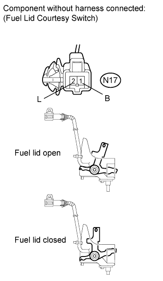
Remove the slide door half open stopper control assembly (fuel lid courtesy switch) (Click here).
-
Measure the resistance according to the value(s) in the table below.
Standard Resistance Tester Connection Door Lock Condition Specified Condition N17-1 (B) - N17-2 (L) OFF (Fuel lid open) 10 kΩ or higher N17-1 (B) - N17-2 (L) ON (Fuel lid closed) Below 1 Ω
- OKClick here
- NGClick here
-
- Click here
CHECK WIRE HARNESS AND CONNECTOR (MAIN SWITCH - POWER SLIDE DOOR ECU LH)
-
Disconnect the N16 power slide door ECU LH connector.
-
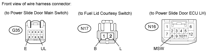
Measure the resistance according to the value(s) in the table below.
Standard Resistance Tester Connection Condition Specified Condition N17-1 (B) - N16-8 (MSW) Always Below 1 Ω G35-9 (UL) - N17-2 (L) Always Below 1 Ω G35-6 (E) - Body ground Always Below 1 Ω G35-9 (UL) - Body ground Always 10 kΩ or higher N17-1 (B) - Body ground Always 10 kΩ or higher
- OKClick here
- NGClick here
-
- Click here
PROCEED TO NEXT SUSPECTED AREA SHOWN IN PROBLEM SYMPTOMS TABLEClick here
- Click here
REPLACE POWER SLIDE DOOR MAIN SWITCHClick here
- Click here
REPAIR OR REPLACE HARNESS OR CONNECTOR
- Click here
REPLACE SLIDE DOOR MOTOR UNIT RHClick here
- Click here
REPLACE POWER SLIDE DOOR MAIN SWITCHClick here
- Click here
REPLACE SLIDE DOOR HALF OPEN STOPPER CONTROL ASSEMBLY (FUEL LID COURTESY SWITCH)Click here
- Click here
REPAIR OR REPLACE HARNESS OR CONNECTOR
- Click here
REPLACE SLIDE DOOR MOTOR UNIT LHClick here