POWER SLIDE DOOR SYSTEM Power Slide Door Control Switch Circuit
DESCRIPTION
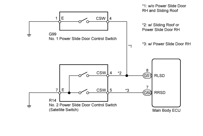
When the main body ECU receives the ON signal from the power slide door control switch, it operates the power slide door motor to "OPEN" or "CLOSE".
WIRING DIAGRAM
INSPECTION PROCEDURE
PROCEDURE
-
CHECK FOR DTC (ALL)
-
Connect the intelligent tester to the DLC3.
-
Turn the engine switch on (IG).
-
Check for DTCs of all systems by following the prompts on the intelligent tester screen.
-
Check if the CAN communication system is functioning normally.
Result Result Proceed to CAN DTCs are not output A CAN DTCs are output B
B 
GO TO CAN COMMUNICATION SYSTEM Click here
A 
-
-
READ VALUE USING INTELLIGENT TESTER
-
Enter the following menus: Body / Main Body / Data List.
-
Check if the power slide door control switch is functioning properly.
Main Body (Main Body ECU) Tester Display Measurement Item / Range Normal Condition Diagnosis Note Rear Right Slide Door Switch*1 Power slide door control switch signal / ON or OFF ON: Power slide door control switch (for RH) pressed
OFF: Power slide door control switch (for RH) not pressed
- Rear Left Slide Door Switch Power slide door control switch signal / ON or OFF ON: Power slide door control switch (for LH) is pressed
OFF: Power slide door control switch (for LH) is not pressed
-
-
*1: w/ Power Slide Door RH
OK The intelligent tester should display as shown in the table according to switch operation. -
NG 
INSPECT POWER SLIDE DOOR CONTROL SWITCH Click here
OK 
PROCEED TO NEXT SUSPECTED AREA SHOWN IN PROBLEM SYMPTOMS TABLE Click here
-
-
INSPECT POWER SLIDE DOOR CONTROL SWITCH
-
w/ Power Slide Door RH or Sliding Roof
-
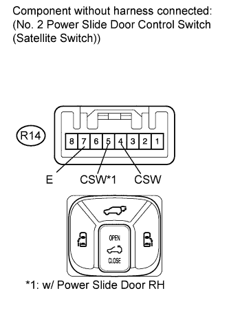
Remove the No. 2 power slide door control switch (satellite switch) Click here.
-
Measure the resistance according to the value(s) in the table below.
Standard Resistance Tester Connection Switch Condition Specified Condition R14-4 (CSW) - R14-7 (E) Pushed (for LH) Below 1 Ω R14-4 (CSW) - R14-7 (E) OFF 10 kΩ or higher R14-5 (CSW) - R14-7 (E)*1 Pushed (for RH) Below 1 Ω R14-5 (CSW) - R14-7 (E)*1 OFF 10 kΩ or higher
-
*1: w/ Power Slide Door RH
-
-
-
w/o Power Slide Door RH and Sliding Roof
-
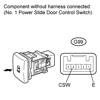
Remove the No. 1 power slide door control switch Click here.
-
Measure the resistance according to the value(s) in the table below.
Standard Resistance Tester Connection Switch Condition Specified Condition G99-4 (CSW) - G99-1 (E) Pushed Below 1 Ω G99-4 (CSW) - G99-1 (E) OFF 10 kΩ or higher Result Result Proceed to OK A NG (w/ Power Slide Door RH or Sliding Roof) B NG (w/o Power Slide Door RH and Sliding Roof) C
-
B
REPLACE NO. 2 POWER SLIDE DOOR CONTROL SWITCH (SATELLITE SWITCH) Click here
C
REPLACE NO. 1 POWER SLIDE DOOR CONTROL SWITCH Click here
A
-
-
CHECK WIRE HARNESS AND CONNECTOR (POWER SLIDE DOOR SWITCH - MAIN BODY ECU AND BODY GROUND)
-
Disconnect the G50*1 and G51 main body ECU connectors.
-
*1: w/ Power Slide Door RH
-
-
Measure the resistance according to the value(s) in the table below.
Standard Resistance Tester Connection Condition Specified Condition R14-4 (CSW) - G51-8 (RLSD)*1 Always Below 1 Ω R14-5 (CSW) - G50-7 (RRSD)*2 Always Below 1 Ω G99-4 (CSW) - G51-8 (RLSD)*3 Always Below 1 Ω R14-7 (E) - Body ground Always Below 1 Ω G99-1 (E) - Body ground*3 Always Below 1 Ω G51-8 (RLSD) - Body ground Always 10 kΩ or higher G50-7 (RRSD) - Body ground Always 10 kΩ or higher
-
*1: w/ Power Slide Door RH or Sliding Roof
-
*2: w/ Power Slide Door RH
-
*3: w/o Power Slide Door RH and Sliding Roof
-
NG
REPAIR OR REPLACE HARNESS OR CONNECTOR
OK
REPLACE MAIN BODY ECU Click here
-