POWER SLIDE DOOR SYSTEM Power Slide Door Sensor RH Circuit
DESCRIPTION
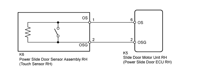
When the power slide door sensor assembly RH (touch sensor RH) sends a jam detection signal to the slide door motor unit RH (power slide door ECU RH), the ECU stops the close operation of the power slide door.
WIRING DIAGRAM
INSPECTION PROCEDURE
PROCEDURE
-
READ VALUE USING INTELLIGENT TESTER (PSD TOUCH SENSOR)
-
Connect the intelligent tester to the DLC3.
-
Turn the engine switch on (IG).
-
Enter the following menus: Body / Rear Right Door / Data List.
-
Check if the touch sensor is functioning properly.
Rear Right Door (Power Slide Door ECU RH) Tester Display Measurement Item / Range Normal Condition Diagnosis Note PSD Touch Sensor Power slide door touch sensor signal / OFF, ON or Open OFF: Power slide door touch sensor not pressed
ON: Power slide door touch sensor pressed
Open: Power slide door touch sensor open
- OK The intelligent tester should display as shown in the table according to touch sensor operation.
NG 
INSPECT POWER SLIDE DOOR SENSOR ASSEMBLY RH (TOUCH SENSOR RH) Click here
OK 
PROCEED TO NEXT SUSPECTED AREA SHOWN IN PROBLEM SYMPTOMS TABLE Click here
-
-
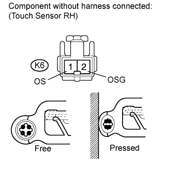
INSPECT POWER SLIDE DOOR SENSOR ASSEMBLY RH (TOUCH SENSOR RH)
-
Remove the power slide door sensor assembly RH (touch sensor RH) Click here.
-
Measure the resistance according to the value(s) in the table below.
Standard Resistance Tester Connection Condition Specified Condition K6-1 (OS) - K6-2 (OSG) Pressed Below 100 Ω K6-1 (OS) - K6-2 (OSG) Free 0.95 to 1.05 kΩ
NG 
REPLACE POWER SLIDE DOOR SENSOR ASSEMBLY RH (TOUCH SENSOR RH) Click here
OK 
-
-
CHECK NO. 1 REAR DOOR WIRE (TOUCH SENSOR RH - ECU RH AND BODY GROUND)
-
Disconnect the K5 power slide door ECU RH connector.
-
Measure the resistance according to the value(s) in the table below.
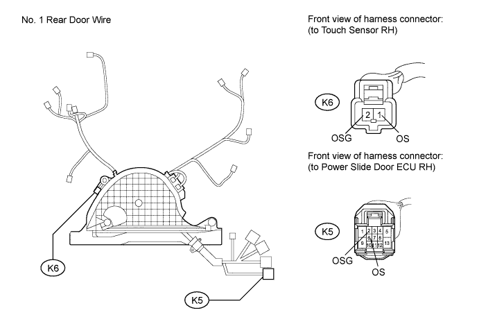
Standard Resistance Tester Connection Condition Specified Condition K6-1 (OS) - K5-6 (OS) Always Below 1 Ω K6-2 (OSG) - K5-2 (OSG) Always Below 1 Ω K6-1 (OS) - Body ground Always 10 kΩ or higher K6-2 (OSG) - Body ground Always 10 kΩ or higher
NG
REPAIR OR REPLACE NO. 1 REAR DOOR WIRE Click here
OK
REPLACE SLIDE DOOR MOTOR UNIT RH Click here
-