- Click here
INSTALL NO. 2 WINDSHIELD GLASS STOPPER
-
Using a brush or a sponge, coat the application area of the No. 2 windshield glass stoppers with Primer G.
Note:
-
Do not apply too much primer.
-
Allow the primer to dry for 3 minutes or more.
-
Throw away any leftover primer.
Tip:If an area other than that specified is coated by accident, wipe off the primer with a clean piece of cloth before it dries.
-
-
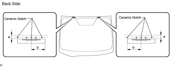
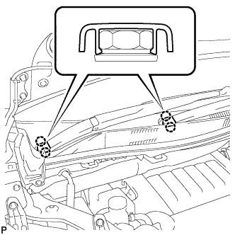
Install 2 new No. 2 windshield glass stoppers onto the windshield glass, as shown in the illustration.
Standard Dimension Area Dimension a 13.1 mm (0.515 in.) b 40.0 mm (1.575 in.) Note:Only the 2-piece type No. 1 windshield glass stoppers are supplied. Use the 2-piece type stoppers even if the 1-piece type stoppers were used.
-
- Click here
INSTALL NO. 1 WINDSHIELD GLASS STOPPER
-
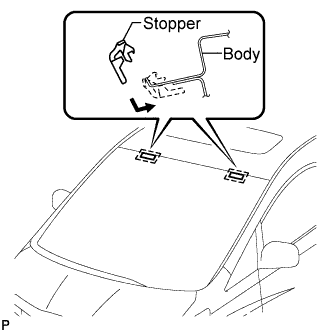
Install 2 new No. 1 windshield glass stoppers to the vehicle body, as shown in the illustration.
Note:Only the 2-piece type No. 1 windshield glass stoppers are supplied. Use the 2-piece type stoppers even if the 1-piece type stoppers were used.
-
- Click here
INSTALL WINDSHIELD GLASS ADHESIVE DAM
-
Using a brush or a sponge, coat the application area of the windshield glass adhesive dam with Primer G.
Note:
-
Do not apply too much primer.
-
Allow the primer to dry for 3 minutes or more.
-
Throw away any leftover primer.
Tip:If an area other than that specified is coated by accident, wipe off the primer with a clean piece of cloth before it dries.
-
-
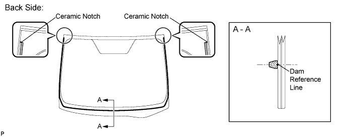
Install a new adhesive dam onto the windshield glass, as shown in the illustration.
Note:Install the new adhesive dam along the dam reference line.
-
- Click here
INSTALL UPPER OUTSIDE WINDSHIELD MOULDING
-
Using a brush or a sponge, coat the application area of the upper outside windshield moulding with Primer G.
Note:
-
Do not apply too much primer.
-
Allow the primer to dry for 3 minutes or more.
-
Throw away any leftover primer.
Tip:If an area other than that specified is coated by accident, wipe off the primer with a clean piece of cloth before it dries.
-
-

Install a new upper outside windshield moulding onto the windshield glass, as shown in the illustration.
Note:Install the new adhesive dam along the dam reference line.
-
- Click here
INSTALL WINDSHIELD GLASS
-
Position the windshield glass.
-
Using suction cups, place the windshield glass in the correct position.
-
Check that the whole contact surface of the windshield glass rim is perfectly even.
-
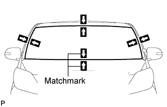
Align the matchmarks on the windshield glass and vehicle body.
Note:Check that the windshield glass stoppers are attached to the vehicle body correctly.
-
Remove the windshield glass.
-
-
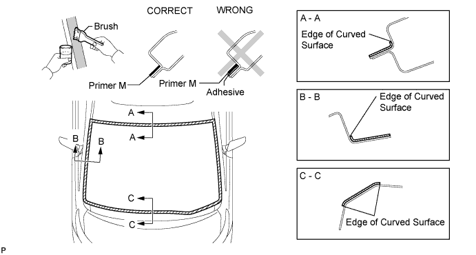
Using a brush, coat the installation surface on the vehicle body with Primer M.
Note:
-
Do not coat the adhesive with Primer M.
-
Do not apply too much primer.
-
Allow the primer to dry for 3 minutes or more.
-
Throw away any leftover primer.
Tip:If an area other than that specified is coated by accident, wipe off the primer with a clean piece of cloth before it dries.
-
-
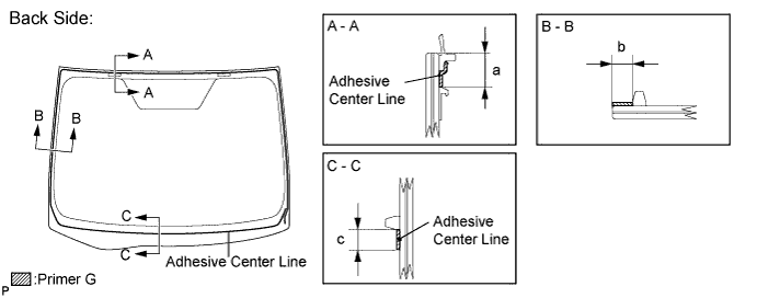
Using a brush or a sponge, coat the application area of adhesive with Primer G.
Standard Dimension Area Dimension a 13.1 mm (0.515 in.) b 8.0 mm (0.315 in.) c 11.0 mm (0.433 in.) Note:
-
Do not apply too much primer.
-
Allow the primer to dry for 3 minutes or more.
-
Throw away any leftover primer.
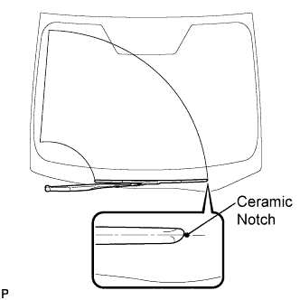
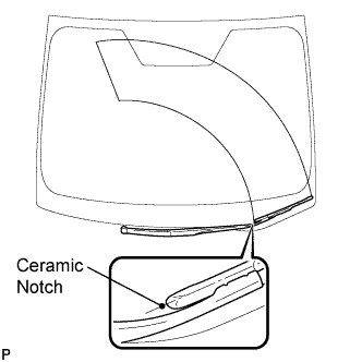
Tip:
-
Apply Primer G onto the ceramic notches.
-
If an area other than that specified is coated by accident, wipe off the primer with a clean piece of cloth before it dries.
-
-
Apply adhesive to the glass.
Adhesive Toyota Genuine Windshield Glass Adhesive or equivalent
-
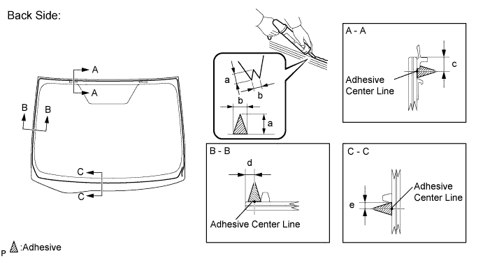
Cut off the tip of the cartridge nozzle as shown in the illustration.
Tip:After cutting off the tip, use all adhesive within the time described in the table below.
Usage Time Frame Temperature Usage Time Frame 35°C (95°F) 15 minutes 20°C (68°F) 1 hour and 40 minutes 5°C (41°F) 8 hours -
Load the sealer gun with cartridge.
-
Apply adhesive to the windshield glass, as shown in the illustration.
Standard Dimension Area Dimension a 12.0 mm (0.472 in.) b 8.0 mm (0.315 in.) c 9.5 mm (0.374 in.) d 6.2 mm (0.244 in.) e 4.0 mm (0.157 in.) Tip:Apply adhesive onto the ceramic notches.
-
-
Install the windshield glass assembly.
-
Using suction cups, position the windshield glass so that the matchmarks are aligned, and press it in gently along the rim.
Note:
-
Check that the windshield glass stoppers are attached to the vehicle body correctly.
-
Check the clearance between the vehicle body and windshield glass.
-
-
Lightly press the front surface of the windshield glass to ensure that the windshield glass is securely fit to the vehicle body.
Tip:Press the glass with a force of 98 N (10 kgf, 22 lbf) or more.
-

Using a scraper, remove any excess or protruding adhesive.
Tip:Apply adhesive onto the windshield glass rim.
-
Hold the windshield glass using protective tape until applied adhesive becomes hard.
Note:Do not drive the vehicle for the time described in the table below.
Minimum Time Temperature Minimum Time prior to Driving Vehicle 35°C (95°F) 1 hour and 30 minutes 20°C (68°F) 5 hours 5°C (41°F) 24 hours
-
-
for Windshield Deicer:
-
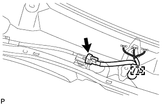
Engage the clamp.
-
Connect the connector.
-
-
- Click here
INSPECT FOR LEAK AND REPAIR
-
After the adhesive has hardened, apply water from the outside of the vehicle. Check that no water leaks into the cabin.
-
If water leaks into the cabin, allow the water to dry and add adhesive.
-
Remove the protective tape.
-
- Click here
INSTALL ROOF HEADLINING ASSEMBLY
-
Return the front section of the roof headlining assembly to the original position.
-
- Click here
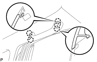
INSTALL VISOR HOLDER
-
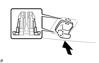
Engage the 2 claws.
-
Push in the visor holder as shown in the illustration.
Tip:Use the same procedure for the LH side and RH side.
-
- Click here
INSTALL VISOR ASSEMBLY RH
-
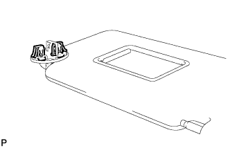
Install the visor assembly RH with 2 new visor arm set clips.
-
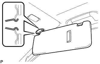
Engage the 2 clips to install the visor assembly RH.
-
- Click here
INSTALL VISOR BRACKET COVER RH
-
Engage the 4 claws to install a new visor bracket cover RH.
-
- Click here
INSTALL VISOR ASSEMBLY LH
Tip:Use the same procedure for the RH side and LH side.
- Click here
INSTALL VISOR BRACKET COVER LH
Tip:Use the same procedure for the RH side and LH side.
- Click here
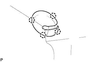
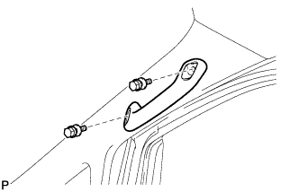
INSTALL ASSIST GRIP SUB-ASSEMBLY
Tip:Use the same procedure for the other rear assist grip.
-
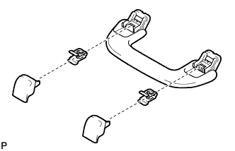
Assemble the assist grip sub-assembly as shown in the illustration.
-
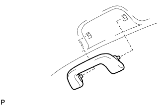
Install the assist grip sub-assembly.
-
- Click here
INSTALL INNER REAR VIEW MIRROR ASSEMBLY (w/o EC Mirror)
-
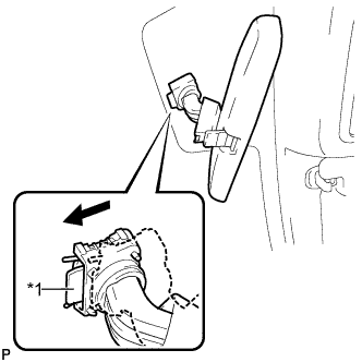
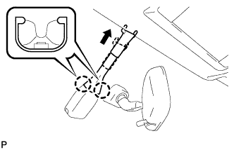
Slide the inner rear view mirror assembly in the direction indicated by the arrow in the illustration to install it.
Table 1. Text in Illustration *1 Lock Lever Note:Confirm that the lock lever is surely installed.
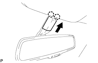
-
Engage the 2 claws to install the inner mirror base cover.
-
- Click here
INSTALL INNER REAR VIEW MIRROR ASSEMBLY (w/ EC Mirror)
-
w/o Automatic High Beam System:
-
Using a T20 "TORX" socket wrench, install the inner rear view mirror assembly with the screw.
1.5 N*m 15 kgf*cm 13 in.*lbf -
Connect the connector.
-
-
w/ Automatic High Beam System:
Note:
-
Do not touch the camera lens (built into the inner rear view mirror assembly) with a bare hand.
-
Do not allow anything to adhere to the camera lens (built into the inner rear view mirror assembly).
-
Do not apply strong impacts to the inner rear view mirror assembly.
-
Do not allow any liquid to get on the inner rear view mirror assembly.
-
Using a T20 "TORX" socket wrench, install the inner rear view mirror assembly with the screw.
1.5 N*m 15 kgf*cm 13 in.*lbf -
Connect the connector.
-
-
- Click here
INSTALL INNER REAR VIEW MIRROR STAY HOLDER COVER (w/ EC Mirror)
-
Engage the 2 claws.
-
Slide the inner rear view mirror stay holder cover and engage the 2 claws to install the cover as shown in the illustration.
-
- Click here
INSTALL RAIN SENSOR (w/ Rain Sensor)
-
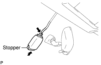
Connect the connector.
-
Gradually attach the rain sensor to the glass surface to prevent air bubbles from forming between them.
-
Push in the stopper.
Note:
-
Do not touch the sensor tape surface or the glass surface directly with your fingers.
-
Clean up dirt on the glass with a piece of cloth, etc.
-
After installing the rain sensor, there should be no air bubbles between the windshield glass and the rain sensor tape.
-
-
- Click here
INSTALL RAIN SENSOR COVER (w/ Rain Sensor)
-
Engage the 2 claws.
-
Install the rain sensor cover as shown in the illustration.
-
- Click here
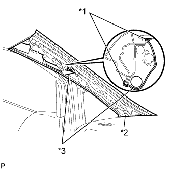
INSTALL FRONT PILLAR GARNISH RH
-
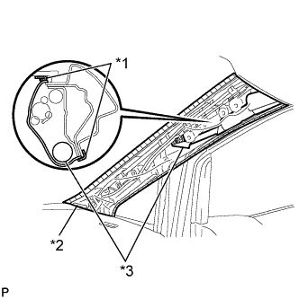
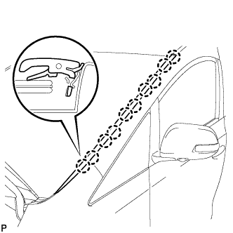
Remove the protective cover.
Table 2. Text in Illustration *1 Protective Tape *2 Protective Cover *3 Curtain Shield Airbag Assembly -
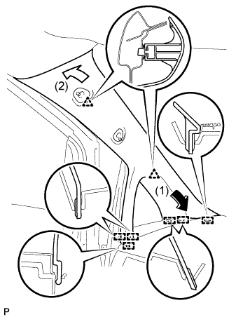
Engage the 6 guides and 2 clips to install the front pillar garnish RH.
-
- Click here
INSTALL NO. 1 ASSIST GRIP (for RH Side)
-
Install the No. 1 assist grip with the 2 bolts.
-
- Click here
INSTALL ASSIST GRIP PLUG (for Front RH)
-
Engage the 4 claws to install the 2 assist grip plugs.
-
- Click here
INSTALL FRONT DOOR OPENING TRIM WEATHERSTRIP RH
-
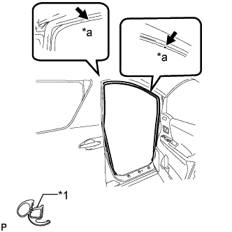
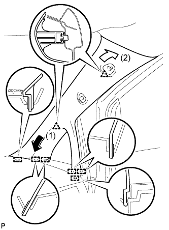
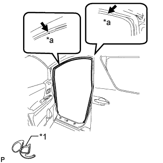
Align the alignment marks on the weatherstrip with the protruding portions on the body indicated by the arrows in the illustration, and install the front door opening trim weatherstrip RH.
Table 3. Text in Illustration *1 Alignment Mark *a White Note:After installation, check that the corners fit correctly.
-
- Click here
INSTALL FRONT PILLAR GARNISH LH
-
Remove the protective cover.
Table 4. Text in Illustration *1 Protective Tape *2 Protective Cover *3 Curtain Shield Airbag Assembly -
Engage the 6 guides and 2 clips, then install the front pillar garnish LH.
-
- Click here
INSTALL NO. 1 ASSIST GRIP
Tip:Use the same procedure for the RH side and LH side.
- Click here
INSTALL ASSIST GRIP PLUG (for Front LH)
Tip:Use the same procedure for the RH side and LH side.
- Click here
INSTALL FRONT DOOR OPENING TRIM WEATHERSTRIP LH
-
Align the alignment marks on the weatherstrip with the protruding portions on the body indicated by the arrows in the illustration, and install the front door opening trim weatherstrip LH.
Table 5. Text in Illustration *1 Alignment Mark *a Yellow Green Note:After installation, check that the corners fit correctly.
-
- Click here
INSTALL ROOF DRIP SIDE FINISH MOULDING LH
-
Engage the 10 claws to install the roof drip side finish moulding.
-
- Click here
INSTALL ROOF DRIP SIDE FINISH MOULDING RH
Tip:Use the same procedure for the RH side and LH side.
- Click here
INSTALL COWL TOP VENTILATOR LOUVER SUB-ASSEMBLY
-
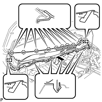
Engage the 15 claws and 2 guides to install the cowl top ventilator louver sub-assembly as shown in the illustration.
-
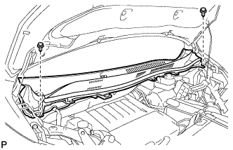
Install the 2 clips.
-
- Click here
INSTALL FRONT WIPER ARM AND BLADE ASSEMBLY RH
-
Operate the wiper and stop the windshield wiper motor at the automatic stop position.
-
When reusing the front wiper arm and blade assembly RH:
-
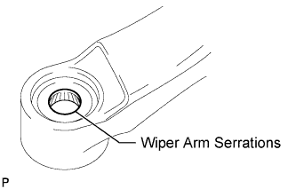
Clean the wiper arm serrations.
-
-
When reusing the windshield wiper link assembly:
-
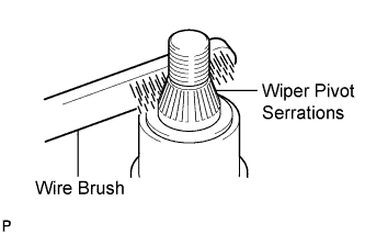
Clean the wiper pivot serrations with a wire brush.
-
-
Install the front wiper arm and blade assembly RH with the nut to the position shown in the illustration.
24 N*m 245 kgf*cm 18 ft.*lbf
-
- Click here
INSTALL FRONT WIPER ARM AND BLADE ASSEMBLY LH
-
When reusing the front wiper arm and blade assembly LH:
-
Clean the wiper arm serrations.
-
-
When reusing the windshield wiper link assembly:
-
Clean the wiper pivot serrations with a wire brush.
-
-
Install the front wiper arm and blade assembly LH with the nut to the position shown in the illustration.
24 N*m 245 kgf*cm 18 ft.*lbf -
Operate the front wipers while spraying washer fluid onto the windshield. Make sure that the front wipers function properly and the wipers do not come into contact with the vehicle body.
-
- Click here
INSTALL WINDSHIELD WIPER ARM COVER
-
Engage the 2 claws to install the 2 windshield wiper arm covers.
-