UPPER INSTRUMENT PANEL REASSEMBLY

-
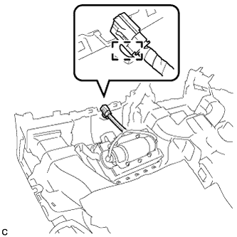
INSTALL AUTOMATIC LIGHT CONTROL SENSOR
-
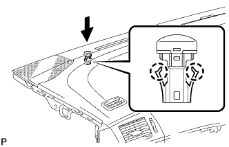
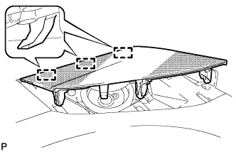
Engage the 2 claws to install the automatic light control sensor.
-
Connect the connector.
-
-
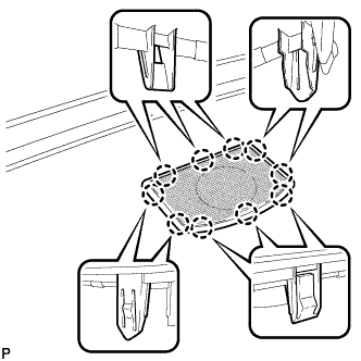
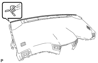
INSTALL FRONT PASSENGER AIRBAG ASSEMBLY
-
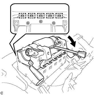
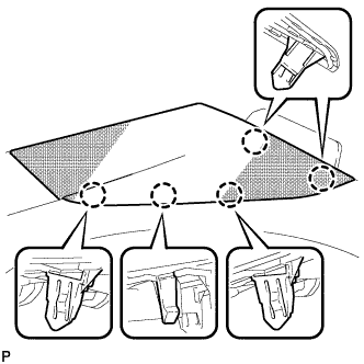
Engage the 5 hooks.
-
Turn the front passenger airbag assembly in the direction indicated by the arrow shown in the illustration.
-
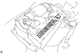
Engage the 5 hooks and install the front passenger airbag assembly on the instrument panel.
-
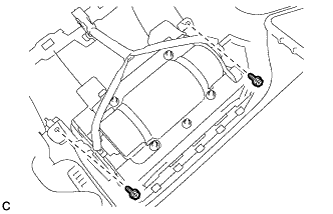
Install the 2 screws.
-
Engage the wire harness clamp.
-
-
INSTALL ION GENERATOR BRACKET (w/ Ion Generator)
-
Engage the 2 guides.
-
Install the ion generator bracket with the 2 screws <B>.
-
-
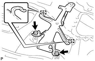
INSTALL NO. 1 ION GENERATOR SUB-ASSEMBLY (w/ Ion Generator)
-
Install the No. 1 ion generator sub-assembly with the 3 screws.
- Torque:
- 2.8 N*m { 29 kgf*cm, 25 in.*lbf }
-
Engage the clamp.
-
Connect the connector.
-
-
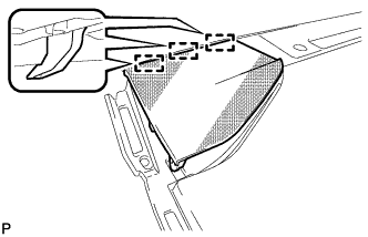
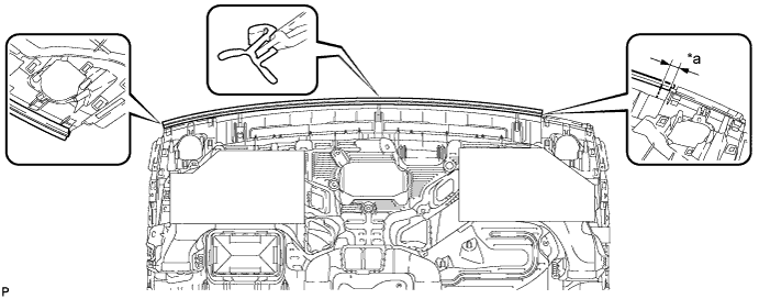
INSTALL AIR DUCT SUB-ASSEMBLY (w/ Ion Generator)
-
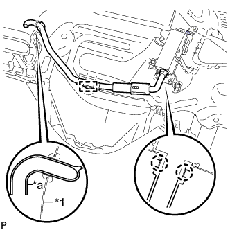
Text in Illustration *1 Instrument Panel Duct Sub-assembly *a End of Air Duct Sub-assembly Engage the 2 claws and clamp to install the air duct sub-assembly.
-
Insert the end of the air duct sub-assembly to the instrument panel duct sub-assembly as shown in the illustration.
-
-
INSTALL FRONT NO. 2 SPEAKER ASSEMBLY RH
-
Connect the connector.
-
Install the front No. 2 speaker assembly with the 2 bolts.
-
-
INSTALL FRONT NO. 2 SPEAKER ASSEMBLY LH
Tech Tips
Use the same procedure as for the RH side.
-
INSTALL FRONT NO. 3 SPEAKER ASSEMBLY (w/ Front Center Speaker)
-
Install the front No. 3 speaker assembly with the 2 screws.
-
Connect the connector.
-
-
INSTALL NO. 2 INSTRUMENT PANEL WIRE
-
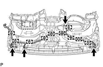
Engage each clamp and install the No. 2 instrument panel wire.
-
Connect each connector.
-
-
INSTALL NAVIGATION ANTENNA ASSEMBLY (w/ Navigation System)
-
Install the navigation antenna assembly with the 2 screws.
-
Engage the 5 clamps.
-
-
INSTALL LOWER NO. 3 INSTRUMENT PANEL CUSHION
-
Align the lower No. 3 instrument panel cushion with the scribed line and install a new lower No. 3 instrument panel cushion.
-
-
INSTALL LOWER NO. 2 INSTRUMENT PANEL CUSHION
-
Align the lower No. 2 instrument panel cushion with the scribed line and install a new lower No. 2 instrument panel cushion.
-
-
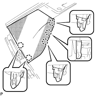
INSTALL NO. 1 INSTRUMENT PANEL SPEAKER PANEL SUB-ASSEMBLY
-
Engage the 3 guides.
-
Engage the 5 claws to install the No. 1 instrument panel speaker panel sub-assembly.
-
-
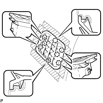
INSTALL NO. 3 INSTRUMENT PANEL SPEAKER PANEL SUB-ASSEMBLY (w/ Front Center Speaker)
-
Engage the 10 claws to install the No. 3 instrument panel speaker panel sub-assembly.
-
-
INSTALL NO. 2 INSTRUMENT PANEL SPEAKER PANEL SUB-ASSEMBLY
-
Engage the 3 guides.
-
Engage the 5 claws to install the No. 2 instrument panel speaker panel sub-assembly.
-
-
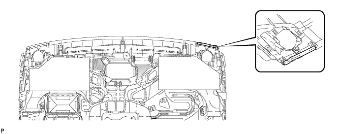
INSTALL SIDE DEFROSTER NOZZLE RH
-
Engage the 8 claws to install the side defroster nozzle RH.
-
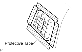
Remove the protective tape from the upper instrument panel sub-assembly.
-
-
INSTALL SIDE DEFROSTER NOZZLE LH
-
Engage the 8 claws to install the side defroster nozzle LH.
-
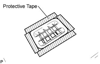
Remove the protective tape from the upper instrument panel sub-assembly.
-
-
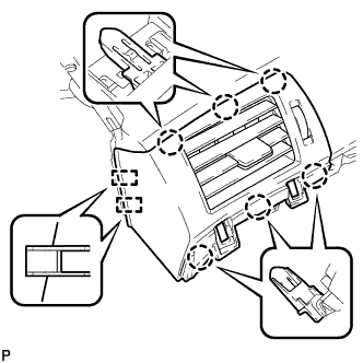
INSTALL NO. 1 INSTRUMENT PANEL REGISTER ASSEMBLY
-
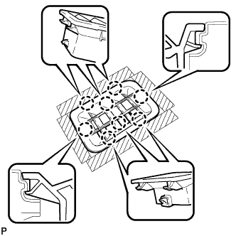
Engage the 6 claws and 2 guides to install the No. 1 instrument panel register assembly.
Note
When installing the No. 1 instrument panel register assembly, make sure to only push on the areas around the claws to avoid damage.
-
-
INSTALL CENTER INSTRUMENT PANEL REGISTER ASSEMBLY
-
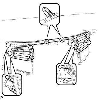
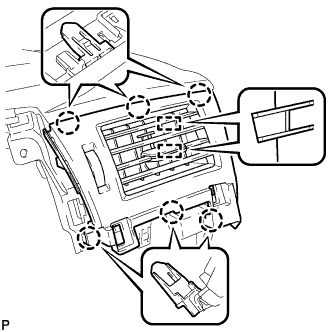
Engage the 10 claws to install the center instrument panel register assembly.
Note
When installing the center instrument panel register assembly, make sure to only push on the areas around the claws to avoid damage.
-
-
INSTALL NO. 2 INSTRUMENT PANEL REGISTER ASSEMBLY
-
Engage the 6 claws and 2 guides to install the No. 2 instrument panel register assembly.
Note
When installing the No. 2 instrument panel register assembly, make sure to only push on the areas around the claws to avoid damage.
-
-
INSTALL NO. 1 INSTRUMENT PANEL CUSHION (for LHD)
-
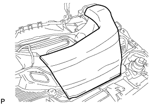
Remove the release paper from a new No. 1 instrument panel cushion.
-
Install the new No. 1 instrument panel cushion to the upper instrument panel sub-assembly as shown in the illustration. Do not apply the cushion beyond the edge of the panel.
-
-
INSTALL INSTRUMENT PANEL CUSHION (for RHD)
-
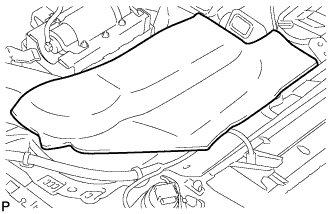
Install the instrument panel cushion.
-
-
INSTALL INSTRUMENT PANEL CUSHION (for LHD)
-
Install the No. 1 instrument panel cushion to the instrument panel sub-assembly as shown in the illustration. Apply the driver side of the cushion to the location shown in the illustration and make sure that the passenger side of the cushion does not protrude beyond the edge of the panel.
Text in Illustration *a 20 mm - -
-