UPPER INSTRUMENT PANEL DISASSEMBLY

-
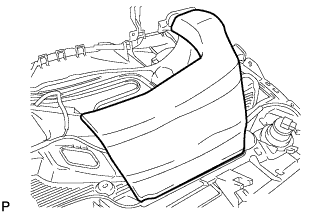
REMOVE INSTRUMENT PANEL CUSHION (for RHD)
-
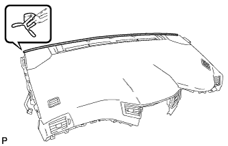
Remove the instrument panel cushion.
-
-
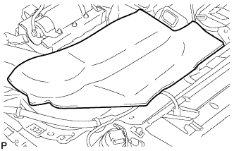
REMOVE INSTRUMENT PANEL CUSHION (for LHD)
-
Remove the instrument panel cushion.
-
-
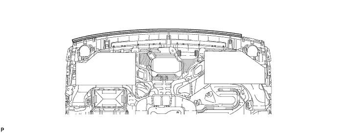
REMOVE NO. 1 INSTRUMENT PANEL CUSHION (for LHD)
-
Remove the No. 1 instrument panel cushion.
Note
Always replace the No. 1 instrument panel cushion with a new one.
-
-
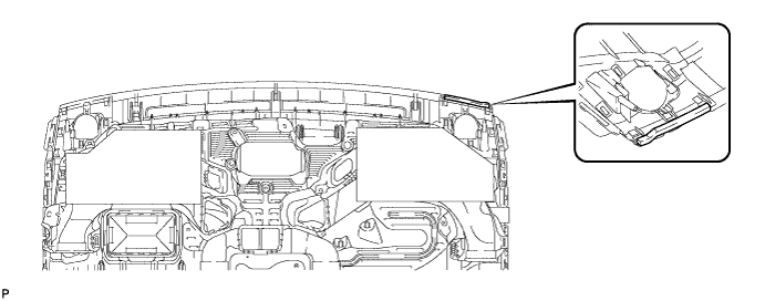
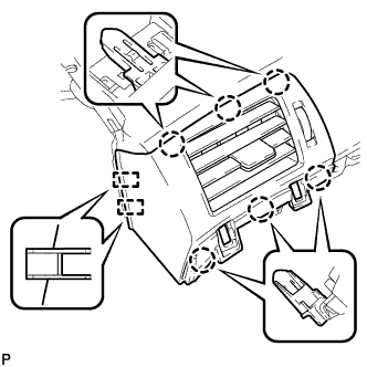
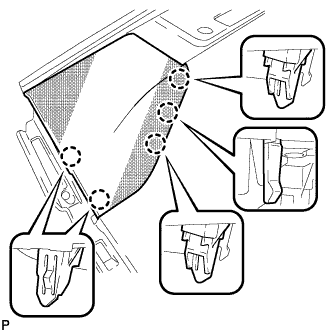
REMOVE NO. 1 INSTRUMENT PANEL REGISTER ASSEMBLY
-
Disengage the 6 claws and 2 guides, and remove the No. 1 instrument panel register assembly.
-
-
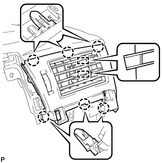
REMOVE CENTER INSTRUMENT PANEL REGISTER ASSEMBLY
-
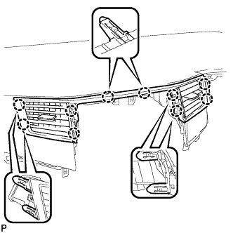
Disengage the 10 claws and remove the center instrument panel register assembly.
Note
Do not use excess force when pulling on the center instrument panel register assembly. Doing so may cause damage.
-
-
REMOVE NO. 2 INSTRUMENT PANEL REGISTER ASSEMBLY
-
Disengage the 6 claws and 2 guides, and remove the No. 2 instrument panel register assembly.
-
-
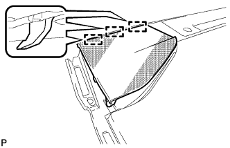
REMOVE SIDE DEFROSTER NOZZLE RH
-
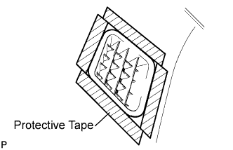
Apply protective tape to the area shown in the illustration.
-
Using a moulding remover, disengage the 8 claws and remove the side defroster nozzle RH.
-
-
REMOVE SIDE DEFROSTER NOZZLE LH
-
Apply protective tape to the area shown in the illustration.
-
Using a moulding remover, disengage the 8 claws and remove the side defroster nozzle LH.
-
-
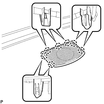
REMOVE NO. 1 INSTRUMENT PANEL SPEAKER PANEL SUB-ASSEMBLY
-
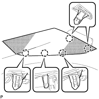
Disengage the 5 claws.
-
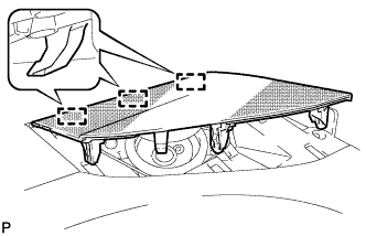
Disengage the 3 guides and remove the No. 1 instrument panel speaker panel sub-assembly.
-
-
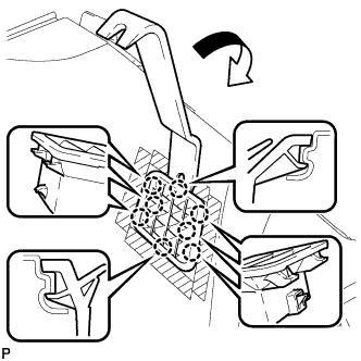
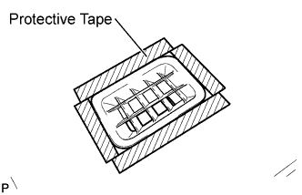
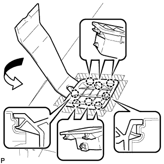
REMOVE NO. 3 INSTRUMENT PANEL SPEAKER PANEL SUB-ASSEMBLY (w/ Front Center Speaker)
-
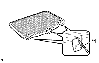
Text in Illustration *1 Protective Tape Using a screwdriver, disengage the 6 claws as shown in the illustration.
Note
When pushing up on the 3 claws, be careful not to damage them. These claws are difficult to disengage.
Tech Tips
Tape the screwdriver tip before use.
-
Disengage the 7 claws and remove the No. 3 instrument panel speaker panel sub-assembly.
-
-
REMOVE NO. 2 INSTRUMENT PANEL SPEAKER PANEL SUB-ASSEMBLY
-
Disengage the 5 claws.
-
Disengage the 3 guides and remove the No. 2 instrument panel speaker panel sub-assembly.
-
-
REMOVE LOWER NO. 3 INSTRUMENT PANEL CUSHION
-
Remove the lower No. 3 instrument panel cushion.
Note
Always replace the lower No. 3 instrument panel cushion with a new one.
-
-
REMOVE LOWER NO. 2 INSTRUMENT PANEL CUSHION
-
Remove the lower No. 2 instrument panel cushion.
Note
Always replace the lower No. 2 instrument panel cushion with a new one.
-
-
REMOVE NAVIGATION ANTENNA ASSEMBLY (w/ Navigation System)
-
Disengage the 5 clamps.
-
Remove the 2 screws and navigation antenna assembly.
-
-
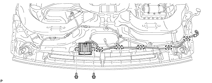
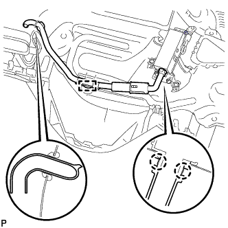
REMOVE NO. 2 INSTRUMENT PANEL WIRE
-
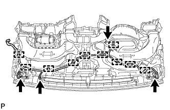
Disconnect each connector.
-
Disengage each clamp and remove the No. 2 instrument panel wire.
-
-
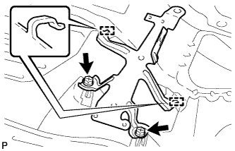
REMOVE FRONT NO. 2 SPEAKER ASSEMBLY RH
-
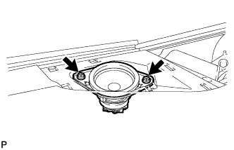
Remove the 2 bolts.
-
Lift the front No. 2 speaker assembly and disconnect the connector to remove the speaker assembly.
Note
Do not touch the cone part of the speaker.
-
-
REMOVE FRONT NO. 2 SPEAKER ASSEMBLY LH
Tech Tips
Use the same procedure as for the RH side.
-
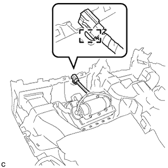
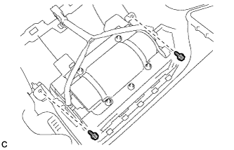
REMOVE FRONT NO. 3 SPEAKER ASSEMBLY (w/ Front Center Speaker)
-
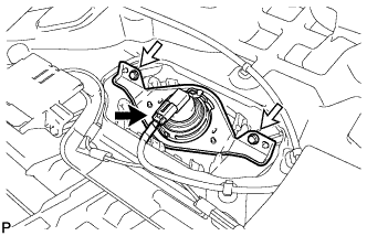
Disconnect the connector.
-
Remove the 2 screws and front No. 3 speaker assembly.
Note
Do not touch the cone part of the speaker.
-
-
REMOVE AIR DUCT SUB-ASSEMBLY (w/ Ion Generator)
-
Disengage the clamp.
-
Disengage the 2 claws and remove the air duct sub-assembly.
-
-
REMOVE NO. 1 ION GENERATOR SUB-ASSEMBLY (w/ Ion Generator)
-
Disconnect the connector.
-
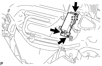
Disengage the clamp.
-
Remove the 3 screws and the No. 1 ion generator sub-assembly.
-
-
REMOVE ION GENERATOR BRACKET (w/ Ion Generator)
-
Remove the 2 screws <B>.
-
Disengage the 2 guides and remove the ion generator bracket.
-
-
REMOVE FRONT PASSENGER AIRBAG ASSEMBLY
-
Disengage the wire harness clamp.
-
Remove the 2 screws.
-
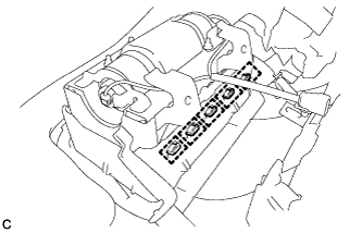
Disengage the 5 hooks.
-
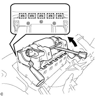
Disengage the 5 hooks to remove the front passenger airbag assembly from the instrument panel safety pad assembly as shown in the illustration.
-
-
REMOVE AUTOMATIC LIGHT CONTROL SENSOR
-
Disconnect the connector.
-
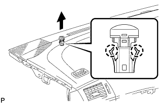
Disengage the 2 claws and remove the automatic light control sensor.
-