ROOF HEADLINING REASSEMBLY

-
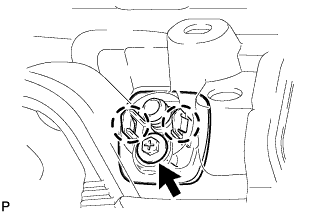
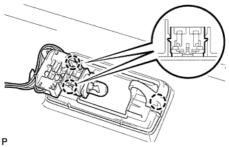
INSTALL SPOT LIGHT ASSEMBLY LH (for Reading Light)
-
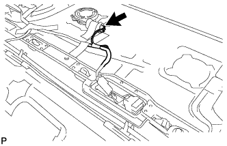
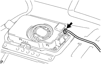
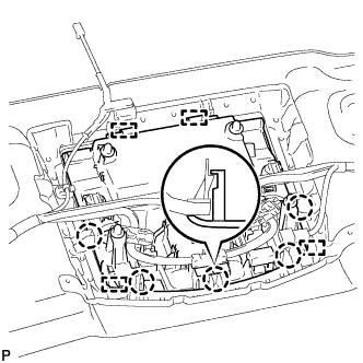
Engage the guide, 2 claws and clip to install the reading light (spot light assembly).
-
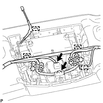
Connect the connector.
-
-
INSTALL SPOT LIGHT ASSEMBLY RH (for Reading Light)
Tech Tips
Use the same procedure for the RH side and LH side.
-
INSTALL NO. 1 ROOF WIRE (w/o Sliding Roof)
-
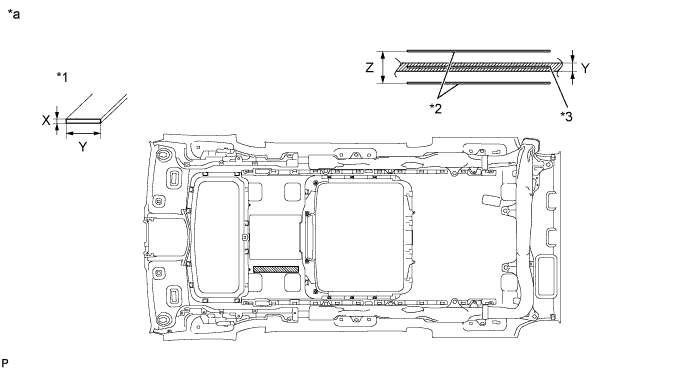
Apply double-sided tape as shown in the illustration.
-
Peel off the release paper from the double-sided tape.
-
Attach the No. 1 roof wire along the double-sided tape so that the marking surface of the wire harness faces downward.
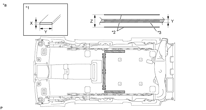
Text in Illustration *1 Double-sided Tape *2 Reference Line *3 Center Line - - *a Tape Attachment Locations (Reference) - - Double-sided Tape size X 1 mm (0.0394 in.) Y 10 mm (0.394 in.) Z 40 mm (1.57 in.) -
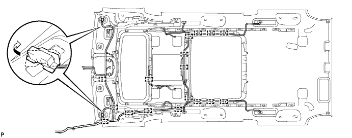
Turn the visor connectors clockwise approximately 90° to install each clamp and the connectors to the roof headlining.
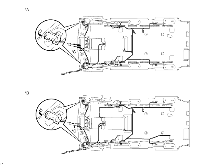
Text in Illustration *A w/o Navigation System for HDD *B w/ Navigation System for HDD *C w/ Rain Sensor *D w/ EC Mirror -
Engage the each claw and connect the No. 1 roof wire to the rear spot light connector.
Tech Tips
Use the same procedure to connect the other rear spot light connectors.
-
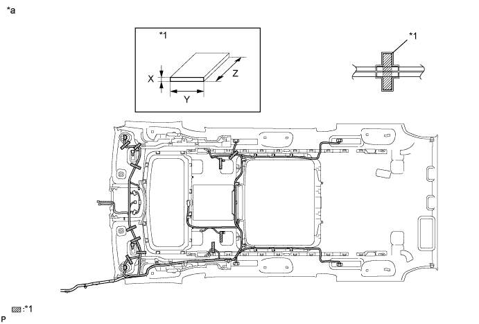
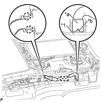
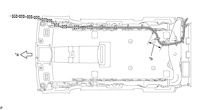
Attach the No. 1 roof wire along the adhesive tape so that the marking surface of the wire harness faces downward.
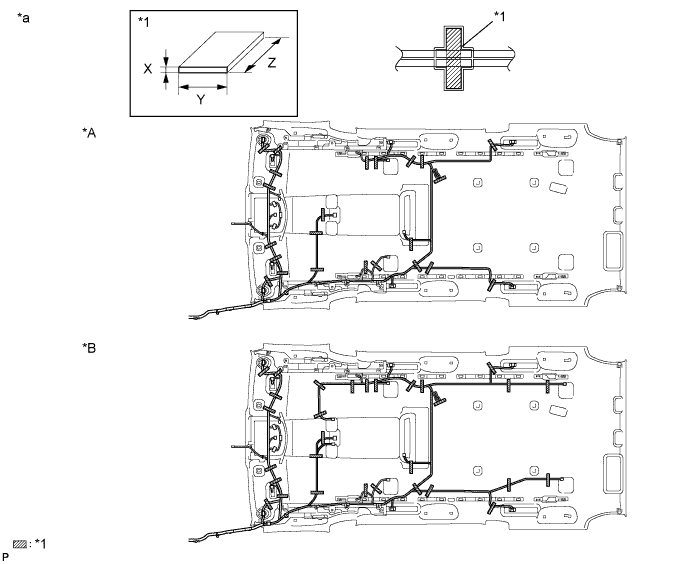
Text in Illustration *A w/o Navigation System for HDD *B w/ Navigation System for HDD *1 Double-sided Tape - - *a Tape Attachment Locations (Reference) - - Adhesive Tape size X 1 mm (0.0394 in.) Y 20 mm (0.787 in.) Z 100 mm (3.94 in.) Note
Securely attach the No. 1 roof wire. Failure to do so may cause abnormal noise.
-
w/o Navigation System for HDD:
-
Connect the connector.
Tech Tips
Use the same procedure for the LH side and RH side.
-
-
-
INSTALL NO. 1 ROOF WIRE (w/ Sliding Roof)
-
Apply double-sided tape as shown in the illustration.
-
Peel off the release paper from the double-sided tape.
-
Attach the No. 1 roof wire along the double-sided tape so that the marking surface of the wire harness faces downward.
Text in Illustration *1 Double-sided Tape *2 Reference Line *3 Center Line - - *a Tape Attachment Locations (Reference) - - Double-sided Tape size X 1 mm (0.0394 in.) Y 10 mm (0.394 in.) Z 40 mm (1.57 in.) -
Turn the visor connectors clockwise approximately 90° to install each clamp and the connectors to the roof headlining.
Text in Illustration *A w/o Navigation System for HDD *B w/ Navigation System for HDD *C w/ Rain Sensor *D w/ EC Mirror -
Engage the each claw and connect the No. 1 roof wire to the rear spot light connector.
Tech Tips
Use the same procedure to connect the other rear spot light connectors.
-
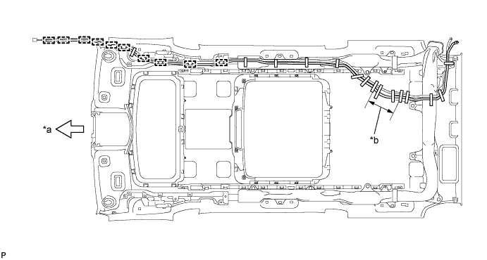
Attach the No. 1 roof wire along the adhesive tape so that the marking surface of the wire harness faces downward.
Text in Illustration *1 Double-sided Tape *2 Reference Line *a Tape Attachment Locations (Reference) - - Adhesive Tape size X 1 mm (0.0394 in.) Y 20 mm (0.787 in.) Z 100 mm (3.94 in.) Note
Securely attach the No. 1 roof wire. Failure to do so may cause abnormal noise.
-
w/o Navigation System for HDD:
-
Connect the connector.
Tech Tips
Use the same procedure for the LH side and RH side.
-
-
for Reading Light:
-
Connect the connector.
Tech Tips
Use the same procedure for the LH side and RH side.
-
-
-
INSTALL ROOF HEADLINING HOLDER COVER (w/ Ion Generator)
-
Engage the 2 claws.
-
Install the roof headlining holder cover with the screw.
-
-
INSTALL NO. 2 ION GENERATOR SUB-ASSEMBLY (w/ Ion Generator)
-
Install the No. 2 ion generator sub-assembly with the 4 screws.
-
Engage the clamp.
-
Connect the connector.
-
-
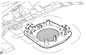
INSTALL REAR AIR DUCT SUB-ASSEMBLY (w/ Ion Generator)
-
Text in Illustration *1 Roof Headlining Holder Cover *a End of Rear Air Duct Sub-assembly *b Cutout Engage the 2 claws and clamp to install the rear air duct sub-assembly.
-
Attach the end of the rear air duct sub-assembly to the roof headlining holder cover as shown in the illustration.
Note
Attach the rear air duct sub-assembly to the roof headlining holder cover with the cutout of the duct facing the RH side of the vehicle.
-
-
INSTALL INTERIOR ILLUMINATION LIGHT ASSEMBLY LH
-
Engage the 12 claws to install the interior illumination light assembly.
-
Install the 2 screws.
-
Connect the connector.
-
-
INSTALL INTERIOR ILLUMINATION LIGHT ASSEMBLY RH
Tech Tips
Use the same procedure for the RH side and LH side.
-
INSTALL REAR CONSOLE BOX LIGHT (NO. 1 INTERIOR ILLUMINATION LIGHT ASSEMBLY) (w/o Sliding Roof)
-
Engage the 2 claws to install the rear console box light (No. 1 interior illumination light assembly).
-
Connect the connector.
-
-
INSTALL REAR CONSOLE BOX LIGHT (NO. 1 INTERIOR ILLUMINATION LIGHT ASSEMBLY) (w/ Sliding Roof)
-
Engage the 2 claws to install the rear console box light (No. 1 interior illumination light assembly).
-
Connect the connector.
-
-
INSTALL NO. 2 ANTENNA CORD SUB-ASSEMBLY (w/o Sliding Roof)
-
Engage the 6 clamps to install the No. 2 antenna cord sub-assembly to the roof headlining assembly as shown in the illustration.
-
-
INSTALL NO. 2 ANTENNA CORD SUB-ASSEMBLY (w/ Sliding Roof)
-
Engage the 6 clamps to install the No. 2 antenna cord sub-assembly to the roof headlining assembly as shown in the illustration.
-
-
INSTALL REAR NO. 2 WASHER HOSE (w/o Sliding Roof)
-
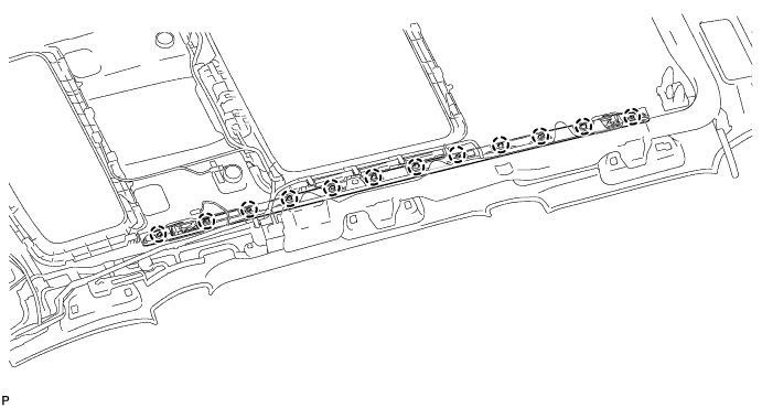
Engage the 10 clamps and install the rear No. 2 washer hose to the roof headlining assembly.
Text in Illustration *a Front Side *b Adjustment Area -
Put the strips of the tape back to the positions shown in the illustration in order to secure the antenna cord and washer hose to the roof headlining assembly.
Tech Tips
-
If the tape has lost adhesion, use other tape, such as packing tape, with enough adhesion to secure the antenna cord and washer hose to the roof headlining assembly.
-
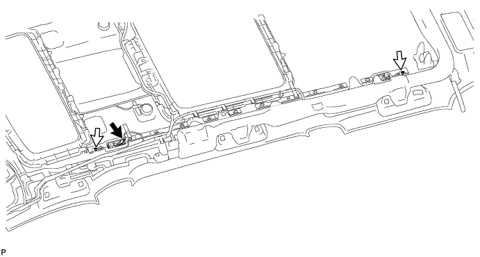
Secure the antenna cord and washer hose to the roof headlining assembly with tape as shown in the illustration.
-
If the entire length of the washer hose is too long, adjust the length by tucking in the hose at the area shown in the illustration.
-
-
-
INSTALL REAR NO. 2 WASHER HOSE (w/ Sliding Roof)
-
Engage the 10 clamps and install the rear No. 2 washer hose to the roof headlining assembly.
Text in Illustration *a Front Side *b Adjustment Area -
Put the strips of the tape back to the positions shown in the illustration in order to secure the antenna cord and washer hose to the roof headlining assembly.
Tech Tips
-
If the tape has lost adhesion, use other tape, such as packing tape, with enough adhesion to secure the antenna cord and washer hose to the roof headlining assembly.
-
Secure the antenna cord and washer hose to the roof headlining assembly with tape as shown in the illustration.
-
If the entire length of the washer hose is too long, adjust the length by tucking in the hose at the area shown in the illustration.
-
-
-
INSTALL MAP LIGHT ASSEMBLY
-
Engage the 4 guides and 5 claws, and install the map light assembly to the roof headlining assembly.
-
Connect the 2 connectors.
-
Engage the 4 clamps.
-
Engage the 8 claws.
-
-
INSTALL VANITY LIGHT ASSEMBLY
-
Engage the 3 claws to install the vanity light assembly.
Tech Tips
Use the same procedure to remove the light on the other side.
-
-
INSTALL CENTER ROOF SPEAKER GRILLE (w/ Navigation System for HDD)
-
Engage the 4 claws and install the center roof speaker grille.
-
-
INSTALL ROOF SPEAKER GRILLE RH (w/ Navigation System for HDD)
-
Engage the 2 claws and install the roof speaker grille RH.
Tech Tips
Use the same procedure to remove the light on the other side.
-
-
INSTALL ROOF SPEAKER GRILLE LH (w/ Navigation System for HDD)
Tech Tips
Use the same procedure for the RH side and LH side.
-
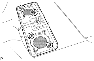
INSTALL ROOF SPEAKER ASSEMBLY (w/ Navigation System for HDD)
-
for Front Side:
-
Engage the 2 claws.
-
Install the roof speaker assembly with the 2 screws.
-
Connect the connector.
-
-
-
INSTALL ROOF SPEAKER ASSEMBLY (w/ Navigation System for HDD)
-
for Center and Rear Side:
-
Engage the 2 claws.
-
Install the roof speaker assembly with the 2 screws.
-
Connect the connector.
-
-
-
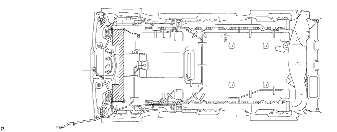
INSTALL NO. 1 ROOF SILENCER PAD (w/o Sliding Roof)
-
Align the markings on the roof headlining assembly with the 3 No. 1 roof silencer pads and install the silencer pads using hot melt glue or double-sided tape as shown in the illustration.
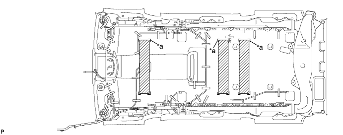
Text in Illustration *a marking - -
-
-
INSTALL NO. 2 ROOF SILENCER PAD (w/o Sliding Roof)
-
Align the markings on the roof headlining assembly with the No. 2 roof silencer pads and install the silencer pads using hot melt glue or double-sided tape as shown in the illustration.
Text in Illustration *a marking - -
-