FRONT EVAPORATOR TEMPERATURE SENSOR INSTALLATION

-
INSTALL NO. 1 COOLER THERMISTOR
-
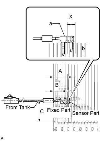
Install the No. 1 cooler thermistor as shown in the illustration.
Part Length A 34.3 mm 1.35 in. B 20.9 mm 0.822 in. C 50 mm 1.96 in. Note
-
Be sure to insert the thermistor only once because reinserting it into the same position will not allow it to be firmly secured.
-
When reusing the evaporator, insert the thermistor one row next to the one that has been used previously (X in the illustration).
-
After inserting the thermistor, do not apply excessive force to the wire.
-
Directly insert the thermistor until the edge of plastic case "a" comes into contact with evaporator "b".
-
-
-
INSTALL NO. 1 COOLER EVAPORATOR SUB-ASSEMBLY
-
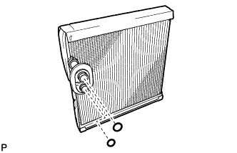
Sufficiently apply compressor oil to 2 new O-rings and the fitting surfaces.
Compressor oil ND-OIL 8 or equivalent -
Install the 2 O-rings to the No. 1 cooler evaporator sub-assembly.
Note
Keep the O-rings and O-ring fitting surfaces free from dirt or any foreign objects.
-
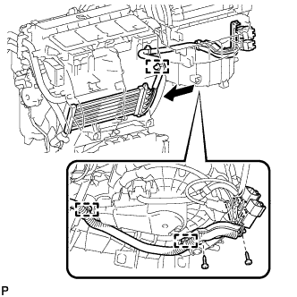
Install the No. 1 cooler evaporator sub-assembly.
-
Engage the clamp.
-
Engage the 5 claws.
-
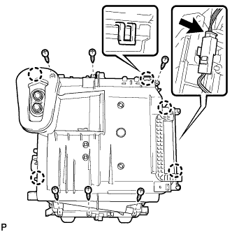
Install the plate cover with the 6 screws.
-
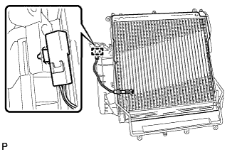
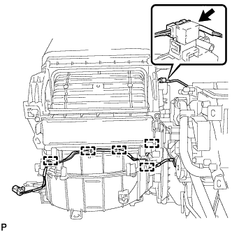
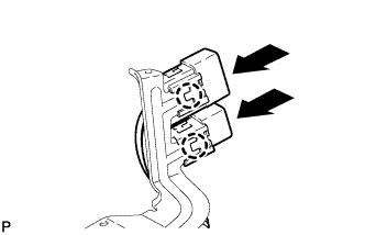
Connect the connector.
-
-
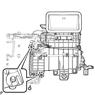
INSTALL COOLER EXPANSION VALVE
-
Using a 4 mm hexagon wrench, install the cooler expansion valve with the 2 hexagon bolts.
- Torque:
- 3.5 N*m { 36 kgf*cm, 31 in.*lbf }
-
-
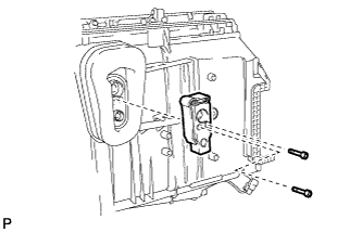
INSTALL BLOWER ASSEMBLY
-
Engage the 2 claws.
-
Install the blower assembly with the 2 screws.
-
Engage each clamp.
-
Connect the connector.
-
-
INSTALL NO. 4 AIR DUCT SUB-ASSEMBLY
-
Engage the 2 claws to install the No. 4 air duct sub-assembly.
-
-
INSTALL DEFROSTER NOZZLE ASSEMBLY
-

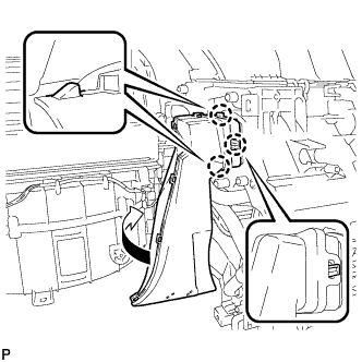
Engage the 4 claws to install the defroster nozzle assembly as shown in the illustration.
-
-
INSTALL QUICK HEATER ASSEMBLY (for Cold Area)
-
Engage the 2 claws to install the 2 quick heater connectors.
-
Install the quick heater assembly with the 2 screws as shown in the illustration.
-
Install the 2 quick heater connectors and the bracket with the 2 screws.
-
Engage each clamp.
-
-
INSTALL NO. 5 AIR DUCT SUB-ASSEMBLY
-
Engage the 3 claws to install the No. 5 air duct sub-assembly as shown in the illustration.
-
-
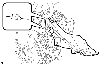
INSTALL AIR CONDITIONING UNIT