FRONT EVAPORATOR TEMPERATURE SENSOR REMOVAL

-
REMOVE AIR CONDITIONING UNIT
-
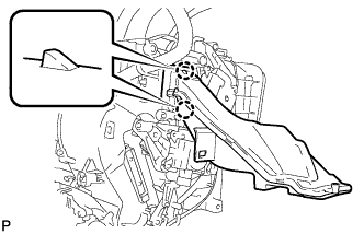
REMOVE NO. 5 AIR DUCT SUB-ASSEMBLY
-
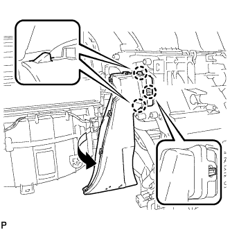
Disengage the 3 claws and remove the No. 5 air duct sub-assembly as shown in the illustration.
-
-
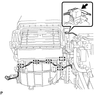
REMOVE QUICK HEATER ASSEMBLY (for Cold Area)
-
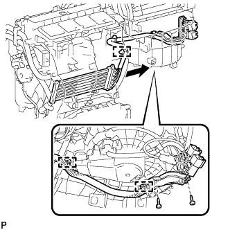
Disengage each clamp.
-
Remove the 2 screws and quick heater connectors and the bracket.
-
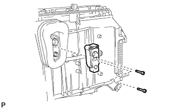
Remove the 2 screws and quick heater assembly as shown in the illustration
-
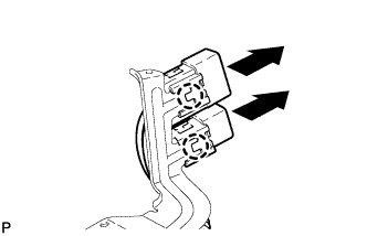
Disengage the 2 claws to separate the 2 quick heater connectors.
-
-
REMOVE DEFROSTER NOZZLE ASSEMBLY
-
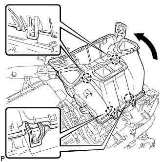
Disengage the 4 claws and remove the defroster nozzle assembly as shown in the illustration.
-
-
REMOVE NO. 4 AIR DUCT SUB-ASSEMBLY
-
Disengage the 2 claws and remove the No. 4 air duct sub-assembly.
-
-
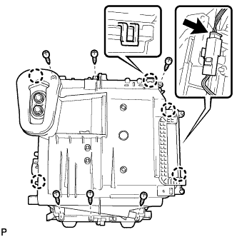
REMOVE BLOWER ASSEMBLY
-
Disengage each clamp.
-
Disconnect the connector.
-
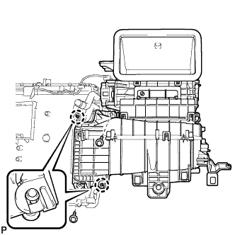
Remove the 2 screws.
-
Disengage the 2 claws and remove the blower assembly.
-
-
REMOVE COOLER EXPANSION VALVE
-
Using a 4 mm hexagon wrench, remove the 2 hexagon bolts and cooler expansion valve.
-
-
REMOVE NO. 1 COOLER EVAPORATOR SUB-ASSEMBLY
-
Disconnect the connector.
-
Remove the 6 screws.
-
Disengage the 5 claws and remove the plate cover.
-
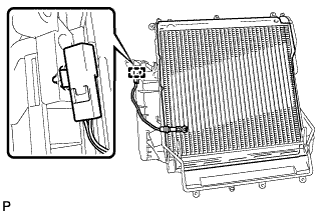
Disengage the clamp and remove the No. 1 cooler evaporator sub-assembly with the No. 1 cooler thermistor.
-
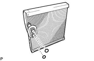
Remove the 2 O-rings from the No. 1 cooler evaporator sub-assembly.
-
-
REMOVE NO. 1 COOLER THERMISTOR
-
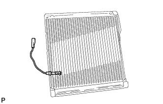
Remove the No. 1 cooler thermistor.
-