AIR CONDITIONING SYSTEM Back-up Power Source Circuit
DESCRIPTION
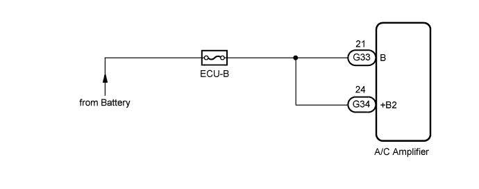
The back-up power source circuit for the A/C amplifier is shown below. Power is supplied even when the engine switch is turned off. The power is used for diagnostic trouble code memory, etc.
WIRING DIAGRAM
INSPECTION PROCEDURE
PROCEDURE
-
INSPECT FUSE (ECU-B)
-
Remove the ECU-B fuse from the No. 1 engine room relay block and junction block.
-
Measure the resistance according to the value(s) in the table below.
Standard Resistance Tester Item Condition Specified Condition ECU-B fuse Always Below 1 Ω
NG 
REPLACE FUSE (ECU-B)
OK 
-
-
CHECK HARNESS AND CONNECTOR (A/C AMPLIFIER - BATTERY)
-
Disconnect the A/C amplifier connector.
-
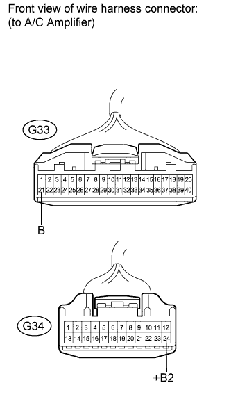
Measure the voltage according to the value(s) in the table below.
Standard Voltage Tester Connection Condition Specified Condition G33-21 (B) - Body ground Always 11 to 14 V G34-24 (+B2) - Body ground Always 11 to 14 V
NG
REPAIR OR REPLACE HARNESS OR CONNECTOR
OK 
PROCEED TO NEXT SUSPECTED AREA SHOWN IN PROBLEM SYMPTOMS TABLE Click here
-