AIR CONDITIONING SYSTEM Rear Blower Motor Circuit
DESCRIPTION
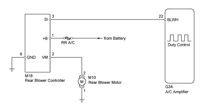
The rear blower motor is operated by signals from the A/C amplifier. Rear blower motor speed signals are transmitted in accordance with changes in the duty ratio.
WIRING DIAGRAM
INSPECTION PROCEDURE
PROCEDURE
-
PERFORM ACTIVE TEST USING INTELLIGENT TESTER
-
Connect the intelligent tester to the DLC3.
-
Turn the engine switch on (IG).
-
Turn the intelligent tester on.
-
Enter the following menus: Body / Air Conditioner / Active Test.
-
Check the operation by referring to the table below.
Air Conditioner Tester Display Test Part Control Range Diagnostic Note Rear Blower Motor Rear blower motor Min.: 0, Max.: 31 - OK Rear blower motor operates and rear blower motor speed level changes. Result Result Proceed to NG (Rear blower motor does not operate) A NG (Rear blower motor operates but does not change speed) B OK C
B 
INSPECT A/C AMPLIFIER Click here
C 
PROCEED TO NEXT SUSPECTED AREA SHOWN IN PROBLEM SYMPTOMS TABLE Click here
A 
-
-
INSPECT FUSE (RR A/C)
-
Remove the RR A/C fuse from the main body ECU.
-
Measure the resistance according to the value(s) in the table below.
Standard Resistance Tester Item Condition Specified Condition RR A/C Always Below 1 Ω
NG
REPLACE FUSE (RR A/C)
OK
-
-
INSPECT REAR BLOWER MOTOR
-
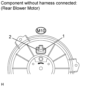
Disconnect the rear blower motor connector.
-
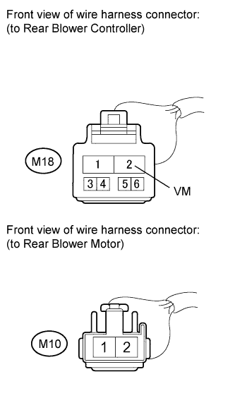
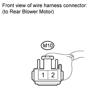
Connect a battery positive (+) lead to terminal 2 and a negative (-) lead to terminal 1, then check that the rear blower motor operates smoothly.
OK The rear blower motor operates smoothly.
NG
REPLACE REAR BLOWER MOTOR Click here
OK
-
-
CHECK HARNESS AND CONNECTOR (REAR BLOWER CONTROLLER - BODY GROUND)
-
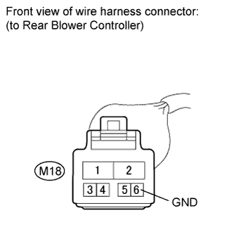
Disconnect the rear blower controller connector.
-
Measure the resistance according to the value(s) in the table below.
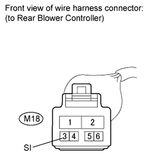
Standard Resistance Tester Connection Condition Specified Condition M18-6 (GND) - Body ground Always Below 1 Ω
NG
REPAIR OR REPLACE HARNESS OR CONNECTOR
OK
-
-
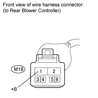
CHECK HARNESS AND CONNECTOR (REAR BLOWER CONTROLLER - BATTERY)
-
Measure the voltage according to the value(s) in the table below.
Standard Voltage Tester Connection Condition Specified Condition M18-1 (+B) - Body ground Always 11 to 14 V
NG
REPAIR OR REPLACE HARNESS OR CONNECTOR
OK
-
-
CHECK HARNESS AND CONNECTOR (REAR BLOWER CONTROLLER - REAR BLOWER MOTOR)
-
Measure the resistance according to the value(s) in the table below.
Standard Resistance Tester Connection Condition Specified Condition M18-2 (VM) - M10-2 Always Below 1 Ω M18-2 (VM) - Body ground Always Below 1 Ω
NG
REPAIR OR REPLACE HARNESS OR CONNECTOR
OK
-
-
CHECK HARNESS AND CONNECTOR (REAR BLOWER MOTOR - BODY GROUND)
-
Measure the resistance according to the value(s) in the table below.
Standard Resistance Tester Connection Condition Specified Condition M10-1 - Body ground Always Below 1 Ω
NG
REPAIR OR REPLACE HARNESS OR CONNECTOR
OK
-
-
CHECK HARNESS AND CONNECTOR (REAR BLOWER CONTROLLER - A/C AMPLIFIER)
-
Disconnect the A/C amplifier connector.
-
Measure the resistance according to the value(s) in the table below.
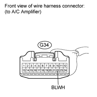
Standard Resistance Tester Connection Condition Specified Condition G34-22 (BLWH) - M18-3 (SI) Always Below 1 Ω G34-22 (BLWH) - Body ground Always 10 kΩ or higher
NG
REPAIR OR REPLACE HARNESS OR CONNECTOR
OK
-
-
INSPECT REAR BLOWER CONTROLLER
-
Reconnect the rear blower controller connector.
-
Measure the voltage according to the value(s) in the table below.
Standard Voltage Tester Connection Condition Specified Condition G34-22 (BLWH) - Body ground Always 4.5 to 5.5 V
NG
REPLACE REAR BLOWER CONTROLLER Click here
OK
-
-
INSPECT A/C AMPLIFIER
-
Reconnect the A/C amplifier connector.
-
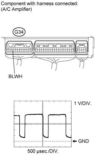
Remove the A/C amplifier with the connectors still connected.
-
Measure the waveform between terminal G34-22 (BLWH) of the A/C amplifier and body ground.
Item Content Tool Setting 1 V/DIV., 500 μsec./DIV. Condition Engine switch on (IG)
Blower switch: LO
OK Waveform is as shown in the illustration. Tech Tips
The waveform varies with the blower level.
NG
REPLACE A/C AMPLIFIER Click here
OK 
REPLACE REAR BLOWER CONTROLLER Click here
-