AIR CONDITIONING SYSTEM, Diagnostic DTC:B14BA

| DTC Code | DTC Name |
|---|---|
| B14BA | Open in Rear Ion Generator Circuit |
DESCRIPTION
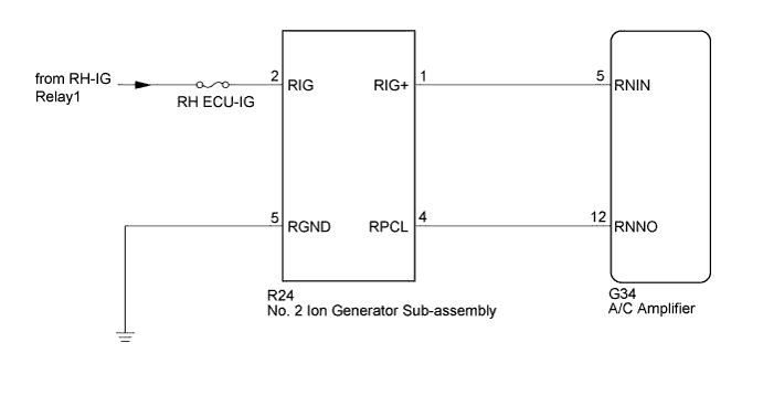
The No. 2 ion generator sub-assembly operates when both the ion generator switch (air purifier switch assembly) and the rear blower switch are on. The A/C amplifier sends a drive signal to the No. 2 ion generator sub-assembly. When the No. 2 ion generator sub-assembly receives the drive signal and starts to operate, it outputs an operation condition signal to the A/C amplifier.
| DTC No. | DTC Detection Condition | Trouble Area |
|---|---|---|
| B14BA | Open in No. 2 ion generator sub-assembly circuit |
|
WIRING DIAGRAM
INSPECTION PROCEDURE
Note
Inspect the fuses for circuits related to this system before performing the following inspection procedure.
PROCEDURE
-
PERFORM ACTIVE TEST USING INTELLIGENT TESTER
-
Connector the intelligent tester to the DLC3.
-
Turn the engine switch on (IG).
-
Turn the intelligent tester on.
-
Enter the following menus: Body / Air Conditioner / Active Test.
-
Check the operation by referring to the table below.
Air Conditioner Tester Display Test Part Control Range Diagnostic Note Ion Generator No. 1 ion generator sub-assembly*1 or No. 2 ion generator sub-assembly*2 OFF, ON -
-
*1: w/ No. 1 Ion Generator Sub-assembly
-
*2: w/ No. 2 Ion Generator Sub-assembly
OK No. 2 ion generator sub-assembly operates normally. Result Result Proceed to NG A OK (When troubleshooting according to Problem Symptoms Table) B OK (When troubleshooting according to the DTC) C -
B 
PROCEED TO NEXT SUSPECTED AREA SHOWN IN PROBLEM SYMPTOMS TABLE Click here
C
REPLACE A/C AMPLIFIER Click here
A 
-
-
CHECK HARNESS AND CONNECTOR (NO. 2 ION GENERATOR SUB-ASSEMBLY - BODY GROUND)
-
Disconnect the G34 A/C amplifier connector.
-
Measure the resistance according to the value(s) in the table below.
Standard Resistance Tester Connection Condition Specified Condition R24-5 (RGND) - Body ground Always Below 1 Ω
NG
REPAIR OR REPLACE HARNESS OR CONNECTOR
OK
-
-
CHECK HARNESS AND CONNECTOR (NO. 2 ION GENERATOR SUB-ASSEMBLY - BATTERY)
-
Measure the voltage according to the value(s) in the table below.
Standard Voltage Tester Connection Condition Specified Condition R24-2 (RIG) - Body ground Engine switch off Below 1 V R24-2 (RIG) - Body ground Engine switch on (IG) 11 to 14 V
NG
REPAIR OR REPLACE HARNESS OR CONNECTOR
OK
-
-
CHECK HARNESS AND CONNECTOR (NO. 2 ION GENERATOR SUB-ASSEMBLY - A/C AMPLIFIER)
-
Disconnect the G34 A/C amplifier connector.
-
Measure the resistance according to the value(s) in the table below.
Standard Resistance Tester Connection Condition Specified Condition G34-5 (RNIN) - R24-1 (RIG+) Always Below 1 Ω G34-12 (RNNO) - R24-4 (RPCL) Always Below 1 Ω G34-5 (RNIN) - Body ground Always 10 kΩ or higher G34-12 (RNNO) - Body ground Always 10 kΩ or higher
NG
REPAIR OR REPLACE HARNESS OR CONNECTOR
OK
-
-
REPLACE NO. 2 ION GENERATOR SUB-ASSEMBLY
-
Replace the No. 2 ion generator sub-assembly Click here.
Tech Tips
Since the No. 2 ion generator sub-assembly cannot be inspected while it is removed from the vehicle, replace the No. 2 ion generator sub-assembly with a new or a known good one and check that the condition returns to normal.
-
Check for the DTC.
Result Result Proceed to DTC B14BA is not output A DTC B14BA is output B
B
REPLACE A/C AMPLIFIER Click here
A 
END (NO. 2 ION GENERATOR SUB-ASSEMBLY WAS DEFECTIVE)
-