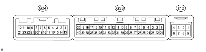
AIR CONDITIONING SYSTEM TERMINALS OF ECU

-
A/C AMPLIFIER
Tech Tips
Check from the rear of the connector while it is connected to the A/C amplifier.
Terminal No.
(Symbol)
Wiring Color Terminal Description Condition Specified Condition G33-1 (IG+) - G33-14 (GND) R - W-B Power source (IG) Engine switch on (IG) 11 to 14 V G33-1 (IG+) - G33-14 (GND) R - W-B Power source (IG) Engine switch off Below 1 V G33-2 (SOL+) - G33-14 (GND) W - W-B A/C compressor solenoid operation signal Engine running
A/C switch: on
Blower switch: LO
Pulse generation
(See waveform 1)
G33-3 (PTC1) - G33-14 (GND)*3 R - W-B PTC heater operation signal Engine is running (650 rpm or higher)
Temperature setting: MAX. HOT
Ambient temperature: 10°C (50°F) or lower
Engine coolant temperature: 75°C (167°F) or lower
Light control switch off
11 to 14 V G33-4 (PTC3) - G33-14 (GND)*3 V - W-B PTC heater operation signal Engine is running (650 rpm or higher)
Temperature setting: MAX. HOT
Ambient temperature: 10°C (50°F) or lower
Engine coolant temperature: 75°C (167°F) or lower
Light control switch off
11 to 14 V G33-5 (TAM) - G33-14 (GND) L - W-B Ambient temperature sensor signal Engine switch on (IG)
Ambient temperature: 25°C (77°F)
1.35 to 1.75 V G33-5 (TAM) - G33-14 (GND) L - W-B Ambient temperature sensor signal Engine switch on (IG)
Ambient temperature: 40°C (104°F)
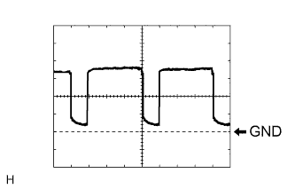
0.9 to 1.2 V G33-6 (DGS) - G34-6 (SG-5)*1 G - Y Smog ventilation sensor signal (HC, CO) After 30 seconds from engine switch on (IG) and sensor exposed to exhaust gas (HC, CO) 1.0 to 4.5 V G33-7 (DGS1) - G34-6 (SG-5)*1 SB - Y Smog ventilation sensor signal (NOx) After 30 seconds from engine switch on (IG) and sensor exposed to exhaust gas (NOx) 1.0 to 4.5 V G33-8 (LOCK) - G33-14 (GND)*2 V - W-B A/C compressor lock sensor signal Engine running
Blower switch: LO
A/C switch: on
Pulse generation
(See waveform 2)
G33-9 (PRE) - G33-13 (SG-2) GR - G A/C pressure sensor signal Start engine, Operate A/C system, Refrigerant pressure: Abnormal pressure (more than 3140 kPa (32.0 kgf/cm2, 455 psi))
4.84 V or higher G33-9 (PRE) - G33-13 (SG-2) GR - G A/C pressure sensor signal Start engine, Operate A/C system, Refrigerant pressure: Abnormal pressure (less than 196 kPa (2.0 kgf/cm2, 28 psi))
Below 0.73 V G33-9 (PRE) - G33-13 (SG-2) GR - G A/C pressure sensor signal Start engine, Operate A/C system, Refrigerant pressure: Normal pressure (less than 3140 kPa (32.0 kgf/cm2, 455 psi) and more than 196 kPa (2.0 kgf/cm2, 28 psi))
0.73 to 4.84 V G33-10 (S5-3) - G33-13 (SG-2) B - G Power supply for A/C pressure sensor Engine switch on (IG)
A/C switch: on
4.75 to 5.25 V G33-10 (S5-3) - G33-13 (SG-2) B - G Power supply for A/C pressure sensor Engine switch on (IG)
A/C switch: off
Below 1 V G33-11 (CANH) - G33-12 (CANL) V - W CAN communication system CAN communication circuit Pulse generation G33-13 (SG-2) - Body ground G - Body ground Ground for A/C pressure sensor, A/C ambient temperature sensor, A/C lock sensor Always Below 1 V G33-14 (GND) - Body ground W-B - Body ground Ground for main power supply Always Below 1 V G33-15 (NAIN) - G33-14 (GND)*4 GR - W-B No. 1 ion generator sub-assembly operation condition signal Engine switch on (IG)
Blower switch: LO
Ion generator switch: on
Below 1 V G33-15 (NAIN) - G33-14 (GND)*4 GR - W-B No. 1 ion generator sub-assembly operation condition signal Engine switch on (IG)
Blower switch: LO
Ion generator switch: off
11 to 14 V G33-20 (MGC) - G33-14 (GND)*2 G - W-B A/C compressor magnetic clutch operation signal Engine switch on (IG)
Blower switch: LO
A/C switch: off
11 to 14 V G33-20 (MGC) - G33-14 (GND)*2 G - W-B A/C compressor magnetic clutch operation signal Engine switch on (IG)
Blower switch: LO
A/C switch: on
Below 1 V G33-21 (B) - G33-14 (GND) SB - W-B Power source (Back-up) Always 11 to 14 V G33-22 (PTC2) - G33-14 (GND)*43 L - W-B PTC heater operation signal Engine is running (650 rpm or higher)
Temperature setting: MAX. HOT
Ambient temperature: 10°C (50°F) or lower
Engine coolant temperature: 75°C (167°F) or lower
Light control switch off
11 to 14 V G33-23 (BLW) - G33-14 (GND) P - W-B Blower motor speed control signal Engine switch on (IG)
Blower switch: on
Pulse generation
(See waveform 3)
G33-28 (RH) - G33-35 (SG-4) L - B Room humidity sensor signal Engine switch on (IG)
Cabin humidity: 40%
1.61 to 2.24 V G33-28 (RH) - G33-35 (SG-4) L - B Room humidity sensor signal Engine switch on (IG)
Cabin humidity: 60%
2.26 to 2.66 V G33-29 (TR) - G33-35 (SG-4) GR - B Room temperature sensor signal Engine switch on (IG)
Cabin temperature: 25°C (77°F)
1.8 to 2.2 V G33-29 (TR) - G33-35 (SG-4) GR - B Room temperature sensor signal Engine switch on (IG)
Cabin temperature: 40°C (104°F)
1.2 to 1.6 V G33-31 (S5-4) - G33-35 (SG-4) R - B Power supply for room humidity sensor Engine switch on (IG) 4.5 to 5.5 V G33-32 (TSP) - G33-14 (GND) V - W-B Solar sensor signal (for Front passenger side) Engine switch on (IG)
Solar sensor subjected to electric light
0.8 to 4.3 V G33-32 (TSP) - G33-14 (GND) V - W-B Solar sensor signal (for Front passenger side) Engine switch on (IG)
Solar sensor covered with a cloth
Below 0.8 V G33-33 (TSD) - G33-14 (GND) R - W-B Solar sensor signal (for Driver side) Engine switch on (IG)
Solar sensor subjected to electric light
0.8 to 4.3 V G33-33 (TSD) - G33-14 (GND) R - W-B Solar sensor signal (for Driver side) Engine switch on (IG)
Solar sensor covered with a cloth
Below 0.8 V G33-34 (SG-1) - Body ground W-B - Body ground Ground for eco switch assembly Always Below 1 V G33-35 (SG-4) - Body ground B - Body ground Ground for room temperature sensor Always Below 1 V G33-36 (ECON) - G33-14 (GND) R - W-B ECO mode switch (eco switch assembly) signal Engine switch on (IG)
ECO mode switch (eco switch assembly): off
11 to 14 V G33-36 (ECON) - G33-14 (GND) R - W-B ECO mode switch (eco switch assembly) signal Engine switch on (IG)
ECO mode switch (eco switch assembly): on
Below 1 V G33-37 (LIN1) - G33-14 (GND) Y - W-B LIN communication signal Engine switch on (IG) Pulse generation G33-38 (RDEF) - G33-14 (GND) R - W-B DEF relay signal Engine switch on (IG)
REAR DEF switch: on
Below 1 V G33-38 (RDEF) - G33-14 (GND) R - W-B DEF relay signal Engine switch on (IG)
REAR DEF switch: off
11 to 14 V G34-1 (RBUS) - G34-21 (RBUG) SB - W BUS IC control signal (for Rear) Engine switch on (IG) Pulse generation G34-4 (TEC) - G34-19 (SGND) R - LG Rear evaporator temperature sensor signal Engine switch on (IG)
Rear evaporator temperature: 0°C (32°F)
2.0 to 2.4 V G34-4 (TEC) - G34-19 (SGND) R - LG Rear evaporator temperature sensor signal Engine switch on (IG)
Rear evaporator temperature: 15°C (59°F)
1.4 to 1.8 V G34-5 (RNIN) - G34-20 (GND2)*5 LG - W-B No. 2 ion generator sub-assembly operation condition signal Engine switch on (IG)
Blower switch: LO
Ion generator switch: on
Below 1 V G34-5 (RNIN) - G34-20 (GND2)*5 LG - W-B No. 2 ion generator sub-assembly operation condition signal Engine switch on (IG)
Blower switch: LO
Ion generator switch: off
11 to 14 V G34-6 (SG-5) - Body ground*1 Y - Body ground Ground for smog ventilation sensor Always Below 1 V G34-7 (SG-6) - Body ground G - Body ground Ground for rear room temperature sensor Always Below 1 V G34-9 (NAI) - G34-20 (GND2)*4, *5 LG - W-B Ion generator switch (air purifier switch assembly) indicator signal Engine switch on (IG)
Blower switch: Lo
Ion generator switch: on
Below 1.5 V G34-9 (NAI) - G34-20 (GND2)*4, *5 LG - W-B Ion generator switch (air purifier switch assembly) indicator signal Engine switch on (IG)
Blower switch: Lo
Ion generator switch: off
10 to 14 V G34-11 (NANO) - G34-20 (GND2)*4 LG - W-B No. 1 ion generator sub-assembly operation signal Engine switch on (IG)
Blower switch: Lo
Ion generator switch: on
Below 1 V G34-11 (NANO) - G34-20 (GND2)*4 LG - W-B No. 1 ion generator sub-assembly operation signal Engine switch on (IG)
Blower switch: Lo
Ion generator switch: off
4.75 to 5.25 V G34-12 (RNNO) - G34-20 (GND2)*5 GR - W-B No. 2 ion generator sub-assembly operation signal Engine switch on (IG)
Blower switch: Lo
Ion generator switch: on
Below 1 V G34-12 (RNNO) - G34-20 (GND2)*5 GR - W-B No. 2 ion generator sub-assembly operation signal Engine switch on (IG)
Blower switch: Lo
Ion generator switch: off
4.75 to 5.25 V G34-13 (RLIN) - G34-20 (GND2) Y - W-B LIN communication signal Engine switch on (IG) Pulse generation G34-17 (TR) - G34-7 (SG-6) B - G Rear room temperature sensor signal Engine switch on (IG)
Cabin temperature: 25°C (77°F)
1.8 to 2.2 V G34-17 (TR) - G34-7 (SG-6) B - G Rear room temperature sensor signal Engine switch on (IG)
Cabin temperature: 40°C (104°F)
1.2 to 1.6 V G34-18 (NASW) - G34-20 (GND2)*4, *5 GR - W-B Ion generator switch (air purifier switch assembly) signal Engine switch on (IG)
Ion generator switch (air purifier switch assembly): on
Below 1 V G34-18 (NASW) - G34-20 (GND2)*4, *5 GR - W-B Ion generator switch (air purifier switch assembly) signal Engine switch on (IG)
Ion generator switch (air purifier switch assembly): off
11 to 14 V G34-19 (SGND) - Body ground LG - Body ground Ground for rear evaporator temperature sensor Always Below 1 V G34-20 (GND2) - Body ground W-B - Body ground Ground for power supply Always Below 1 V G34-21 (RBUG) - Body ground W - Body ground Ground for BUS IC (for Rear) Always Below 1 V G34-22 (BLWH) - G34-20 (GND2) Y - W-B Rear blower motor control signal Engine switch on (IG)
Rear blower switch: on
Pulse generation
(See waveform 4)
G34-23 (RBBU) - G34-21 (RBUG) L - W Power supply for BUS IC (for Rear) Engine switch on (IG) 11 to 14 V G34-24 (+B2) - G34-20 (GND2) SB - W-B Power source (Back-up) Always 11 to 14 V z12-2 (BUS G) - Body ground - Ground for BUS IC Always Below 1 V z12-3 (BUS) - z12-2 (BUS G) - BUS IC control signal Engine switch on (IG) Pulse generation z12-4 (B BUS) - z12-2 (BUS G) - Power supply for BUS IC Engine switch off Below 1 V z12-4 (B BUS) - z12-2 (BUS G) - Power supply for BUS IC Engine switch on (IG) 11 to 14 V z12-5 (SG) - Body ground - Ground for evaporator temperature sensor Always Below 1 V z12-6 (TE) - z12-5 (SG) - A/C evaporator temperature sensor signal Engine switch on (IG)
Evaporator temperature: 0°C (32°F)
1.7 to 2.1 V z12-6 (TE) - z12-5 (SG) - A/C evaporator temperature sensor signal Engine switch on (IG)
Evaporator temperature: 15°C (59°F)
0.9 to 1.3 V
-
*1: w/ Automatic Recirculation Control System
-
*2: for 2GR-FE
-
*3: w/ PTC Heater Assembly
-
*4: w/ No. 1 Ion Generator Sub-assembly
-
*5: w/ No. 2 Ion Generator Sub-assembly
-
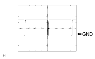
Waveform 1:
Item Content Terminal No. G33-2 (SOL+) - G33-14 (GND) Tool Setting 5 V/DIV., 500 μs/DIV. Vehicle Condition Engine running
A/C switch: on
-
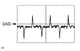
Waveform 2:
Item Content Terminal No. G33-8 (LOCK) - G33-14 (GND) Tool Setting 200 mV/DIV., 10 ms./DIV. Vehicle Condition Engine running
Blower switch: LO
A/C switch: on
-
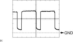
Waveform 3:
Item Content Terminal No. G33-23 (BLW) - G33-14 (GND) Tool Setting 1 V/DIV., 500 μs/DIV. Vehicle Condition Engine switch on (IG)
Blower switch: on
-
Waveform 4:
Item Content Terminal No. G34-22 (BLWH) - G34-20 (GND2) Tool Setting 2 V/DIV., 500 μs/DIV. Vehicle Condition Engine switch on (IG)
Rear blower switch: on
-
-
AIR CONDITIONING CONTROL ASSEMBLY (for Front)

Tech Tips
Check from the rear of the connector while it is connected to the air conditioning control assembly (for front).
Terminal No.
(Symbol)
Wiring Color Terminal Description Condition Specified Condition G26-1 (+B) - G26-4 (GND) R - BR Power source (Back-up) Always 11 to 14 V G26-3 (LIN1) - G26-4 (GND) Y - BR LIN communication signal Engine switch on (IG) Pulse generation G26-4 (GND) - Body ground BR - Body ground Ground for front air conditioning control assembly Always Below 1 V G26-5 (IG+) - G26-4 (GND) R - BR Power source (IG) Engine switch off Below 1 V G26-5 (IG+) - G26-4 (GND) R - BR Power source (IG) Engine switch on (IG) 11 to 14 V G26-6 (ACC) - G26-4 (GND) GR - BR Power source (ACC) Engine switch off Below 1 V G26-6 (ACC) - G26-4 (GND) GR - BR Power source (ACC) Engine switch on (ACC) 11 to 14 V -
INTEGRATION CONTROL AND PANEL ASSEMBLY (REAR A/C CONTROL ASSEMBLY)

Tech Tips
Check from the rear of the connector while it is connected to the integration control and panel assembly (rear A/C control assembly).
Terminal No.
(Symbol)
Wiring Color Terminal Description Condition Specified Condition R9-5 (RLIN) - R9-12 (E) Y - W-B LIN communication signal (for Rear) Engine switch on (IG) Pulse generation R9-7 (IG+) - R9-12 (E) R - W-B Power source (IG) Engine switch off Below 1 V R9-7 (IG+) - R9-12 (E) R - W-B Power source (IG) Engine switch on (IG) 11 to 14 V R9-12 (E) - Body ground W-B - Body ground Ground for rear A/C control assembly Always Below 1 V