AIR CONDITIONING SYSTEM SYSTEM DESCRIPTION

-
GENERAL
The air conditioning system has the following controls:
Control Outline Neural Network Control This control is capable of effecting complex control by artificially simulating the information processing method of the nervous system of living organisms in order to establish a complex input/output relationship that is similar to a human brain. Automatic Recirculation Control*1 Automatically changes the air inlet mode to the fresh air or recirculation air mode according to the level of harmful elements in the outside air, cabin temperature and outside temperature. Pollen Removal Mode Control Activated by the pollen removal mode switch operation. Switches the air vent to the FACE mode. Sends air which has passed through the clean air filter to the area around the upper parts of the bodies of the driver and front passenger. This air is filtered by the clean air filter in order to remove pollen. Outlet Air Temp. Control Based on the temperature set at the temperature control switch, the neural network control calculates the outlet air temperature based on the input signals from various sensors. The temperature setting for the driver, front passenger, rear passengers are controlled independently in order to provide a separate vehicle interior temperature for the right and left sides of the cabin. Thus, air conditioning that accommodates the occupants' preferences has been realized. Blower Control Controls the blower motor in accordance with the airflow volume that has been calculated by the neural network control based on the input signals from various sensors. Air Outlet Control Automatically switches the air outlets in accordance with the outlet mode that has been calculated by the neural network control based on the input signals from various sensors. In accordance with the engine coolant temperature, outside air temperature, amount of sunlight, required blower and vehicle speed conditions, this control automatically switches the blower outlet to the FOOT/DEF mode to prevent the windows from becoming fogged when the outside air temperature is low. Air Inlet Control Automatically controls the air inlet control damper to achieve the calculated outlet air temperature that is required. Drives the servo motor (for air inlet) according to the operation of the air inlet control switch and moves the dampers to the FRESH or RECIRC position. Compressor Control Through the calculation of the target evaporator temperature based on various sensor signals, the A/C amplifier optimally controls the discharge capacity by regulating the opening extent of the A/C compressor solenoid valve.*2 The A/C amplifier compares the A/C pulley speed signals, which are transmitted by the ECM (crankshaft position sensor). When the A/C amplifier determines that the A/C pulley is locked, it turns off the magnetic clutch.*3 Rear Window Defogger Control Switches the rear defogger on for 60 minutes or less when the rear defogger button is pressed. Switches them off if the button is pressed again while they are operating. Eco Mode Control When the Eco switch assembly is turned on, the A/C amplifier limits the air conditioning system performance. Self-diagnosis A Diagnostic Trouble Code (DTC) is stored in the memory when the A/C amplifier detects a problem with the air conditioning system.
-
*1: w/ Automatic Recirculation Control System
-
*2: for 2AZ-FE
-
*3: for 2GR-FE
-
-
NEURAL NETWORK CONTROL
-
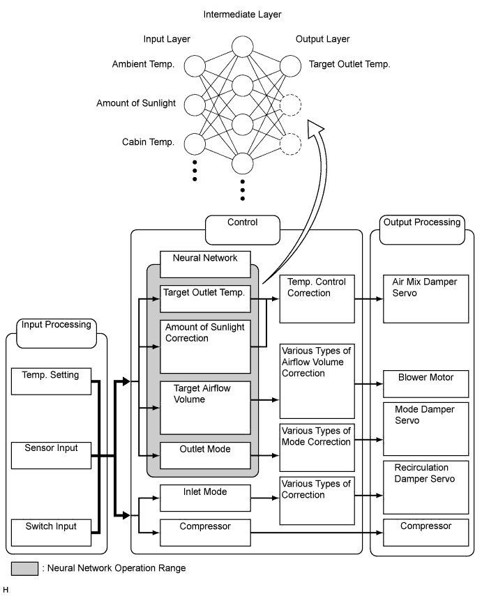
In previous automatic air conditioning systems, the A/C amplifier determined the required outlet air temperature and blower air volume in accordance with the calculation formula that has been obtained based on information received from the sensors.
However, because the senses of a person are rather complex, a given temperature is sensed differently, depending on the environment in which the person is situated. For example, a given amount of solar radiation can feel comfortably warm in a cold climate, or extremely uncomfortable in a hot climate. Therefore, as a technique for effecting a higher level of control, a neural network has been adopted in the automatic air conditioning system. With this technique, the data that has been collected under varying environmental conditions is stored in the A/C amplifier. The A/C amplifier can then effect control to provide enhanced air conditioning comfort.
-
The neural network control consists of neurons in the input layer, intermediate layer and output layer. The input layer neurons process the input data of the outside temperature, the amount of sunlight and the room temperature based on the outputs of the switches and sensors, and output them to the intermediate layer neurons. Based on this data, the intermediate layer neurons adjust the strength of the links among the neurons. The sum of these is then calculated by the output layer neurons in the form of the required outlet temperature, solar correction, target airflow volume and outlet mode control volume. Accordingly, the A/C amplifier controls the servo motors and blower motor in accordance with the control volumes that have been calculated by the neural network control.
-
-
AUTOMATIC RECIRCULATION CONTROL (W/ AUTOMATIC RECIRCULATION CONTROL SYSTEM)
-
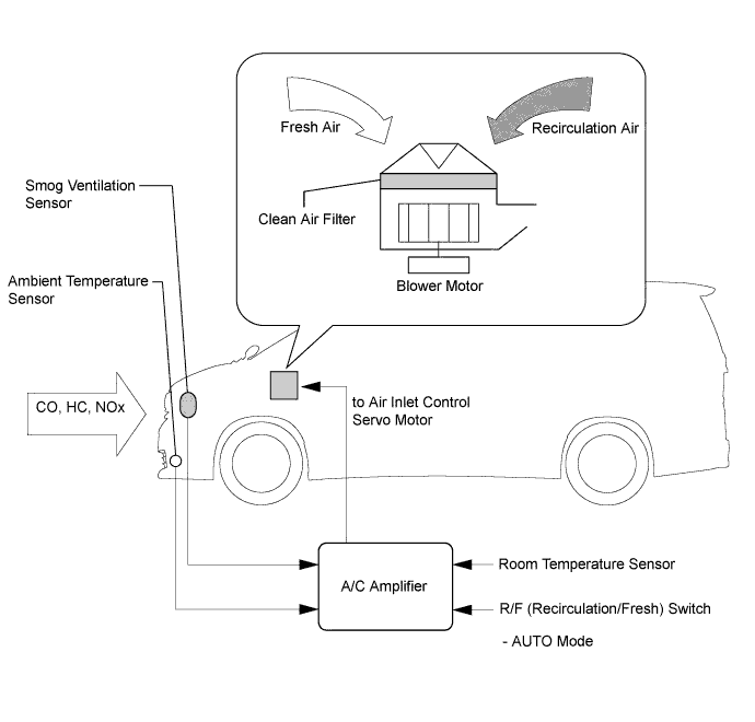
When the automatic recirculation control is operating, the A/C amplifier automatically changes the air inlet mode to the fresh air or recirculate air mode based on signals from the smog ventilation sensor, ambient temperature and room temperature sensors when the AUTO air inlet mode is selected.
-
The A/C amplifier detects harmful elements (CO, HC and NOx) based on a smog ventilation sensor signal and automatically switches the air inlet mode to the recirculate air mode to prevent such harmful elements from entering the cabin.
-
The A/C amplifier detects cabin temperature based on a room temperature sensor signal and automatically switches the air inlet mode to the recirculate air mode to prevent the cabin temperature from becoming too high.
-
The A/C amplifier detects the outside temperature based on an ambient temperature sensor signal and automatically switches the air inlet mode to the fresh air mode to prevent the windshield from fogging up.
Note
The smog ventilation sensor cannot detect elements such as the smoke from a bonfire or factory exhaust, foul or animal odors, and dirt or dust particles. Therefore, the air inlet mode is not switched automatically in accordance with those elements.
-
-
-
POLLEN REMOVAL MODE CONTROL
-
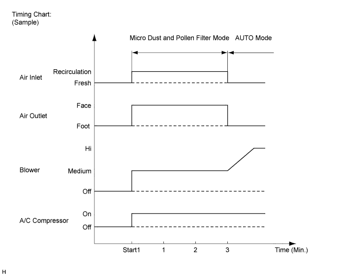
When the pollen removal mode switch is pressed, the pollen removal mode control is activated. Then, the air vent is switched to the FACE mode and recirculated pollen free air flows in the area around the upper parts of the bodies of the driver and front passenger.
-
When the pollen removal mode switch signal is input to the A/C amplifier, the A/C amplifier controls the A/C compressor, air inlet control servo motor, air outlet control servo motor and blower motor as shown in the timing chart.
-
This control usually operates for approximately 3 minutes.
-
After this control stops operating, the A/C amplifier automatically returns to the mode it was in just before the pollen removal mode switch was pressed.
-
-
-
MODE POSITION AND DAMPER OPERATION
-
Mode Position and Damper Operation
-
for Front Air Conditioning
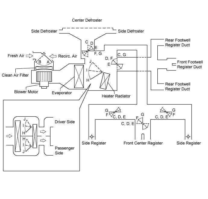
Functions of Main Dampers Control Damper Operation Position Damper Position Operation Air Inlet Control Damper FRESH A Allows fresh air to enter. RECIRC B Causes internal air to recirculate. Air Mix Control Damper MAX COLD to MAX HOT Temperature Setting H, I, J Varies the mixture ratio of the hot air and the cold air in order to regulate the temperature continuously between HOT and COLD. Air Outlet Control Damper DEF

C Defrosts the windshield through the center defroster, side defrosters, while air is also blown out from the side registers. FOOT/DEF

D Defrosts the windshield through the center defroster, side defrosters, while air is also blown out from the front footwell register duct and rear footwell register ducts. In addition, air blows out slightly from the side registers. FOOT

E Air blows out of the footwell register ducts and side registers. In addition, a small amount of air will blow out from the front center register, center defroster and side defrosters.*1 BI-LEVEL

F Air blows out of the front center register, side registers, front footwell register duct and rear footwell register ducts. FACE

G Air blows out of the center register and side registers. *1: When the outlet mode was manually switched to FOOT mode, air does not blow out from the center defroster and side defrosters.
-
for Rear Air Conditioning
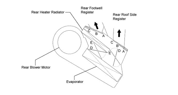
Control Damper Operation Position Damper Position Operation Air Outlet Control Door FACE
A Air blows out from the rear roof side registers. BI-LEVEL
B Air blows out from the rear roof side registers and rear footwell registers. FOOT
C Air blows out from the rear footwell registers. Air Mix Control Damper MAX COLD to MAX HOT Temperature Setting D, E Varies the mixture ratio of the cold air and hot air in order to regulate the temperature continuously from HOT to COLD.
-
-
-
AIR OUTLETS AND AIRFLOW VOLUME
-
Air Outlets and Airflow Volume
-
for Front Registers
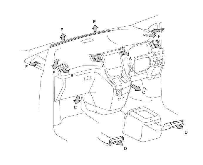
Indication Mode FACE FOOT DEF CTR SIDE FR RR CTR SIDE A B C D E F FACE 

B/L 
FOOT 
F/D DEF The size of the circle ○ indicates the ratio of airflow volume.
-
for Rear Registers
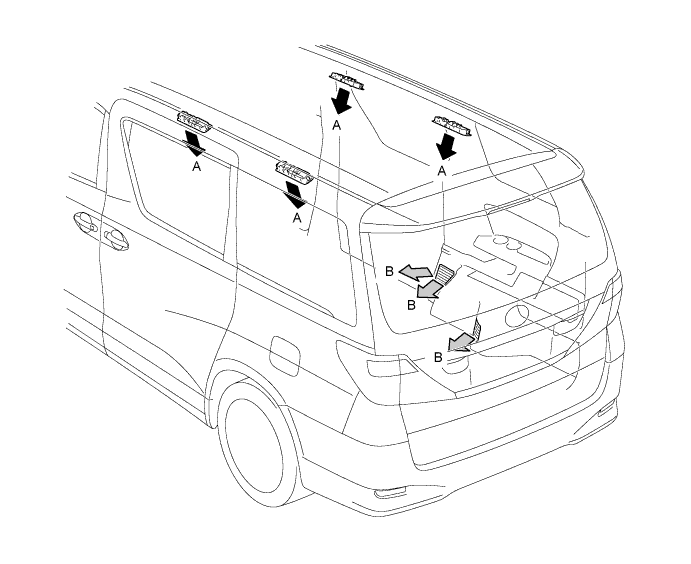
Indication Mode A B FACE B/L FOOT The size of the circle ○ indicates the ratio of airflow volume.
-
-
-
A/C COMPRESSOR
-
General
-
The A/C compressor is a continuously variable capacity type in which its capacity can be varied in accordance with the cooling load of the air conditioning.
-
This compressor consists of the A/C pulley, shaft, lug plate, swash plate, piston, shoe, crank chamber, cylinder and solenoid valve.
-
The A/C pulley with built-in magnetic clutch and the lock sensor that detects whether the magnetic clutch is locked are installed on models with the 2GR-FE.
-
The DL (Damper Limiter) type A/C pulley is installed on models with the 2AZ-FE.
-
A solenoid valve that adjusts the suction pressure so that the compressor capacity can be controlled as desired is provided.
-
The internal valve is provided on models with 2AZ-FE to improve the A/C compressor durability under the high speed and large thermal load conditions. The internal valve is integrated into the solenoid valve.
-
-
Solenoid Valve Operation
-
The crank chamber is connected to the discharge passage. A solenoid valve is provided between the discharge passage (LO pressure) and the discharge passage (HI pressure).
-
The solenoid valve operates under duty cycle control in accordance with the signals from A/C amplifier.
-
When the solenoid valve closes (solenoid coil is energized), a difference in pressure is created and the pressure in the crank chamber decreases. Then, the pressure that is applied to the right side of the piston becomes greater than the pressure that is applied to the left side of the piston. This compresses the spring and tilts the swash plate. As a result, the piston stroke increases and the discharge capacity increases.
-
When the solenoid valve opens (solenoid coil is not energized), the difference in pressure disappears. Then, the pressure that is applied to the left side of the piston becomes the same as the pressure that is applied to the right side of the piston. Thus, the spring elongates and eliminates the tilt of the swash plate. As a result, there is no piston stroke and the discharge capacity is reduced.
-
-
Internal Valve Operation (for 2AZ-FE)
-
The internal valve operates when the A/C compressor speed has increased rapidly, the A/C compressor speed is high, or when thermal load has suddenly changed. As a result, the A/C compressor capacity is reduced, increasing the durability of the A/C compressor.
-
-
DL type A/C Pulley (for 2AZ-FE)
-
This pulley contains a damper to absorb the torque fluctuations of the engine and a limiter mechanism to protect the drive belt in case the compressor locks. In the event that the compressor locks, the limiter mechanism causes the spoke portion of the pulley to break, thus separating the pulley from the compressor.
-
-
-
A/C LOCK SENSOR (for 2GR-FE)
The A/C lock sensor sends A/C pulley speed signals to the A/C amplifier. The A/C amplifier determines whether the A/C compressor is locked or not by using those signals and engine speed signals.
-
EVAPORATOR TEMPERATURE SENSOR
The evaporator temperature sensor detects the temperature of the cool air immediately through the evaporator in the form of resistance changes, and outputs it to the A/C amplifier.
-
BLOWER MOTOR
-
for Front:
The front blower motor has a built-in blower controller, and is controlled using duty control performed by the A/C amplifier.
-
for Rear:
The rear blower motor is controlled using duty control performed by the A/C amplifier.
-
-
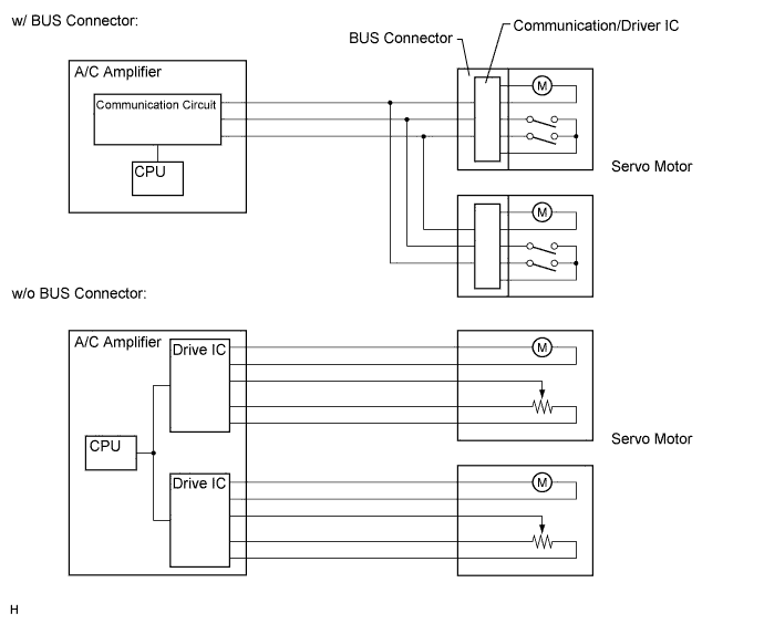
BUS CONNECTOR (AIR CONDITIONING HARNESS)
-
A BUS connector is used in the wire harness connection that connects the servo motor from the A/C amplifier.
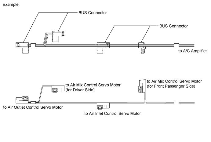
-
Each BUS connector has a built-in communication/driver IC which communicates with each servo motor connector, actuates the servo motor, and has a position detection function. This enables bus communication for the servo motor wire harness, for a more lightweight construction and a reduced number of wires.
-
-
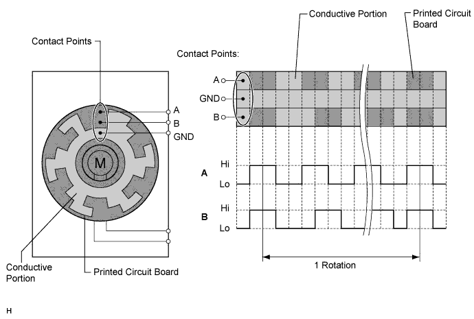
SERVO MOTOR
-
The pulse pattern type servo motor consists of a printed circuit board and a servo motor. The printed circuit board has three contact points, and can transmit two ON-OFF signals to the A/C amplifier based on the difference of the pulse phases. The BUS connector can detect the damper position and movement direction with this signal.
-
-
ROOM TEMPERATURE SENSOR (BUILT-IN HUMIDITY SENSOR)
-
The room temperature sensor detects the cabin temperature based on changes in the resistance of its built-in thermistor and sends a signal to the A/C amplifier.
-
A humidity sensor function has been added to the room temperature sensor. By enabling the detection of humidity in the vehicle interior, this function optimizes the amount of dehumidification effort during the operation of the A/C system. As a result, the power consumption of the compressor has been reduced and a comfortable level of humidity has been realized in the vehicle interior.
-
The humidity-sensing resistance film that is built into the humidity sensor absorbs and releases the humidity in the cabin. During the absorption and releasing processes, the humidity-sensing resistance film expands (during the absorption of humidity) and contracts (during drying). The clearance between the carbon particles in the humidity-sensing resistance film expands and contracts during absorption and drying, thus changing the resistance between the electrodes. The A/C amplifier determines the humidity in the cabin through the changes in the output voltage of the humidity sensor that are caused by the resistance between the electrodes.
-
-
AMBIENT TEMPERATURE SENSOR
The ambient temperature sensor detects the outside temperature based on changes in the resistance of its built-in thermistor and sends a signal to the A/C amplifier.
-
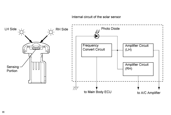
SOLAR SENSOR
-
The solar sensor consists of a photo diode, two amplifier circuits for the solar sensor and frequency converter circuit for the light control sensor.
-
The solar sensor detects (in the form of changes in the current that flows through the built-in photo diode) the changes in the amount of sunlight from the LH and RH sides (2 directions) and outputs these sunlight strength signals to the A/C amplifier.
-
-
A/C PRESSURE SENSOR
The A/C pressure sensor detects the refrigerant pressure and outputs it to the A/C amplifier in the form of voltage changes.
-
SMOG VENTILATION SENSOR (W/ AUTOMATIC RECIRCULATION CONTROL SYSTEM)
-
The smog ventilation sensor detects harmful elements such as CO, HC and NOx present in the air outside of the vehicle. The sensor outputs a signal to the A/C amplifier.
-
The sensitivity of the smog ventilation sensor can be adjusted. Adjustment can be done using the air conditioning control assembly.
-
-
ION GENERATOR CONTROL (W/ ION GENERATOR ASSEMBLY)
CAUTION:
-
Do not attempt to disassemble or repair the ion generator assembly because it contains high voltage parts.
Tech Tips
-
When the ion generator sub-assembly operates, a small amount of ozone is emitted and may be faintly smelled in some situations. However, this is approximately the same as the amount that already exists in nature, such as in forests, and as such has no effect on the human body.
-
A slight noise may be heard during operation. This does not indicate a malfunction.
-
According to temperature and humidity conditions, fan speed and air outlet mode selected, the ion generator assembly may not operate at full capacity.
-
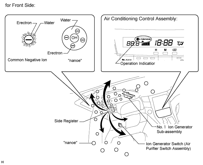
for Front Side
-
The A/C amplifier sends a drive signal to the No. 1 ion generator sub-assembly. When the No. 1 ion generator sub-assembly receives the drive signal and starts to operate, it outputs an operation condition signal to the A/C amplifier.
-
The No. 1 ion generator sub-assembly emits "nanoe" ions that are electrically charged and encapsulated with water. The ions are discharged into the cabin through the driver side vent to provide skin-friendly clean air.
Note
-
Do not insert anything into the driver side vent, attach anything to it, or use sprays around the driver side vent. These things may cause the No. 1 ion generator sub-assembly not to work properly.
Tech Tips
"nanoe" is a trademark of Panasonic Electric Works Co., Ltd.
-
-
-
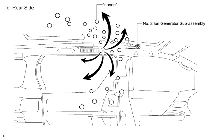
for Rear Side
-
The A/C amplifier sends a drive signal to the No. 2 ion generator sub-assembly. When the No. 2 ion generator sub-assembly receives the drive signal and starts to operate, it outputs an operation condition signal to the A/C amplifier.
-
The No. 2 ion generator sub-assembly emits "nanoe" ions that are electrically charged and encapsulated with water. The ions are discharged into the cabin through the "nanoe" vent on the roof headliner to provide skin-friendly clean air.
Note
-
Do not insert anything into the "nanoe" vent on the roof headliner, attach anything to it, or use sprays around the "nanoe" vent on the roof headliner. These things may cause the No. 2 ion generator sub-assembly not to work properly.
Tech Tips
"nanoe" is a trademark of Panasonic Electric Works Co., Ltd.
-
-
-
-
ECO MODE CONTROL
-
Under the control of eco mode, the A/C amplifier restricts the air conditioning system performance under specified conditions, thus improving fuel economy.
-