REAR AIR CONDITIONING UNIT INSTALLATION

-
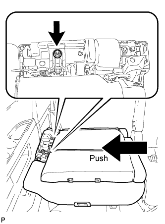
INSTALL REAR COOLING UNIT ASSEMBLY
-
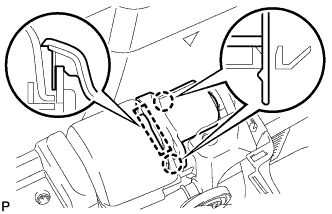
Pass the drain hose through the grommet.
-
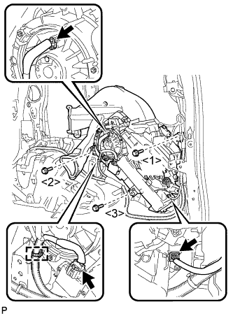
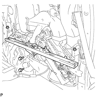
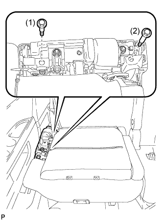
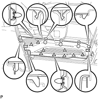
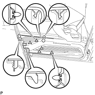
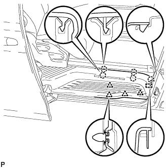
Install the rear cooling unit assembly with the 3 bolts.
- Torque:
- 9.8 N*m { 100 kgf*cm, 87 in.*lbf }
Tech Tips
Tighten the bolts in the order shown in the illustration.
-
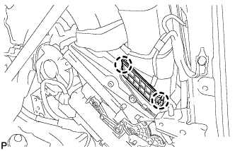
Connect each connector.
-
Engage the clamp.
-
Install the 2 bolts.
- Torque:
- 9.8 N*m { 100 kgf*cm, 87 in.*lbf }
-
-
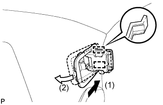
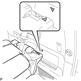
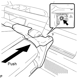
INSTALL DOOR CONTROL RECEIVER
-
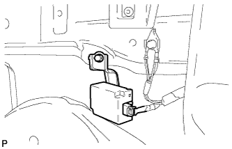
Install the door control receiver with the bolt.
-
Connect the connector.
-
-
INSTALL NO. 1 COOLER AIR DUCT
-
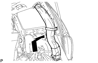
Install the No. 1 cooler air duct as shown in the illustration.
-
Engage the 2 claws to install the cooler plate.
-
-
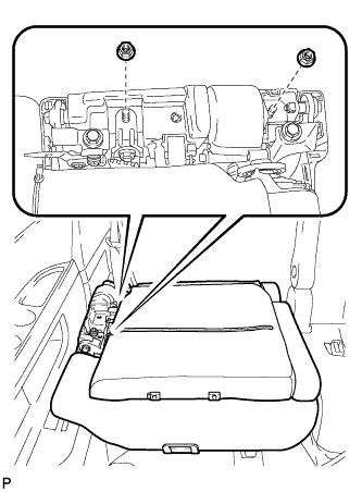
INSTALL REAR NO. 2 SEAT TRACK ASSEMBLY RH
-
Install the rear No. 2 seat track assembly RH with the 2 bolts and 2 nuts.
- Torque:
- 42 N*m { 428 kgf*cm, 31 ft.*lbf }
-
-
INSTALL UPPER ROOF SIDE INNER GARNISH RH
-
Engage the guide, claw and 2 clips to install the upper roof side inner garnish RH.
-
-
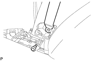
CONNECT REAR NO. 2 SEAT OUTER BELT ASSEMBLY RH
-
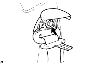
Install the shoulder anchor of the rear No. 2 seat outer belt assembly with the bolt.
- Torque:
- 42 N*m { 428 kgf*cm, 31 ft.*lbf }
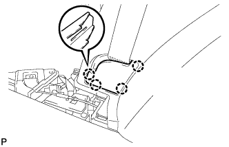
-
Engage the 2 claws to close the cover.
-
-
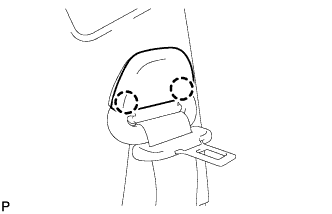
INSTALL REAR SEAT HOOK SUB-ASSEMBLY RH
-
Engage the 2 guides as shown in the illustration.
-
Engage the 4 claws.
-

Install the rear seat hook sub-assembly RH with the 2 bolts.
-
-
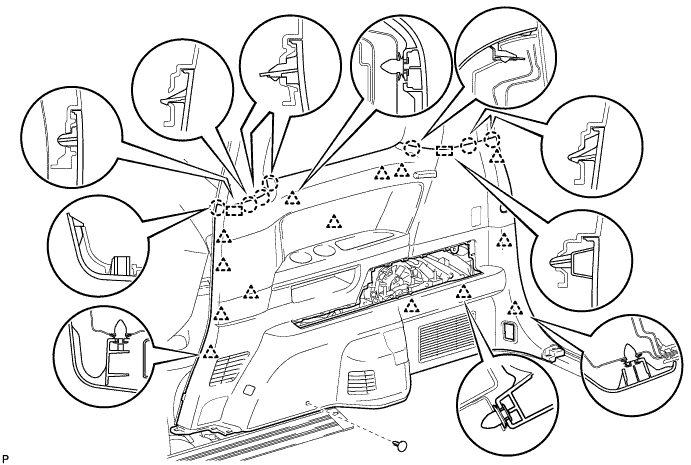
INSTALL REAR QUARTER TRIM PANEL ASSEMBLY RH
-
Connect the connectors.
-
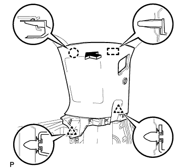
Engage the 2 guides, 7 claws and 14 clips to install the rear quarter trim panel assembly RH.
-
Install the clip(A).
-
-
INSTALL DECK SIDE GARNISH RH
-
Engage the 4 guides and 11 claws to install the deck side garnish RH as shown in the illustration.
-
-
CONNECT REAR NO. 1 SEAT OUTER BELT ASSEMBLY RH (for 60/40 Split Seat Type)
-
Connect the floor end of the rear No. 1 seat outer belt assembly with the bolt.
- Torque:
- 42 N*m { 428 kgf*cm, 31 ft.*lbf }
-
-
INSTALL INNER LUGGAGE COMPARTMENT TRIM COVER RH (for 60/40 Split Seat Type)
-
Engage the 4 claws and install the inner luggage compartment trim cover RH.
-
-
INSTALL ROPE HOOK ASSEMBLY (for RH Side)
-
Install the rope hook assembly with the bolt.
- Torque:
- 6.5 N*m { 66 kgf*cm, 58 in.*lbf }
-
Engage the 2 claws.
-
-
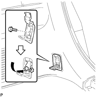
INSTALL NO. 1 LUGGAGE COMPARTMENT TRIM HOOK
-
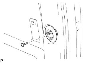
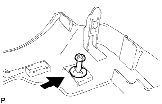
Install the bolt.
-
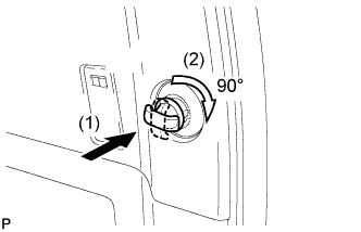
Push in the No. 1 luggage compartment trim and turn it clockwise approximately 90° to install the No. 1 luggage compartment trim hook.
-
-
INSTALL REAR NO. 2 SEAT ASSEMBLY RH
-
Temporary install the rear No. 2 seat assembly.
Note
Do not damage the rear No. 2 seat assembly, body or body interior.
-
Connect the rear No. 2 seat outer belt assembly.
-
Temporary tighten the 2 nuts.
-
Lock the inner leg in the inner rail.
-
Remove the clip of the seat track upper rail cover.
-
Temporary install the seat track upper rail cover.
-
Adjust the rear No. 2 seat assembly so that the positioning marks are aligned as shown in the illustration.
-
As shown in the illustration, tighten the nut while pushing the rear No. 2 seat assembly towards the outside of the vehicle.
- Torque:
- 42 N*m { 428 kgf*cm, 31 ft.*lbf }
Note
-
If this operation is difficult to perform alone, use two or more people.
-
Make sure not to misalign the positioning marks when pushing the seat.
-
If the nut is tightened without the seat pushed towards the outside of the vehicle, the inner lock may not operate normally.
-
Remove the seat track upper rail cover.
-
As shown in the illustration, tighten the nut while pushing the rear No. 2 seat assembly towards the outside of the vehicle, and install the rear No. 2 seat assembly.
- Torque:
- 42 N*m { 428 kgf*cm, 31 ft.*lbf }
Note
-
If this operation is difficult to perform alone, use two or more people.
-
Make sure not to misalign the positioning marks when pushing the seat.
-
If the nut is tightened without the seat pushed towards the outside of the vehicle, the inner lock may not operate normally.
-
After reassembling the seat, check that the inner lock operates normally and that the inner lock and lock cover do not interfere with each other.
-
Check that the rear No. 2 seat flips up and slides smoothly. If abnormal, loosen the 2 nuts and perform operations starting from step (f) again.
-
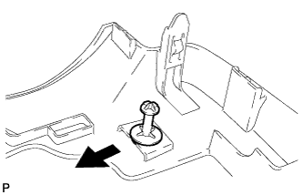
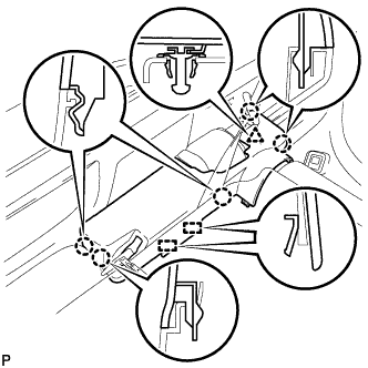
Remove the 2 stopper bolts in the order indicated in the illustration.
Note
Before removing the stopper bolts, make sure that the inner leg is securely locked in the inner rail.
-
-
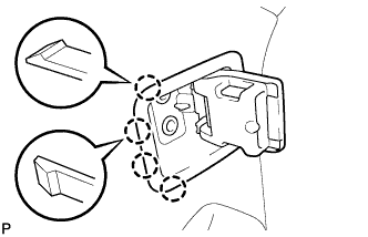
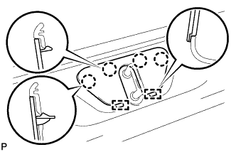
INSTALL NO. 1 SEAT TRACK LOCK PLATE COVER (for RH Side)
-
Engage the 2 claws and guide to install the No. 1 seat track lock plate cover.
-
-
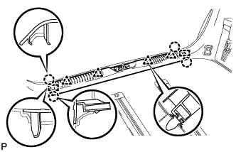
INSTALL UPPER SEAT TRACK RAIL COVER RH
-
Engage the 2 claws to install the grommet.
-
Install the clip of the seat track upper rail cover.
-
Engage the 2 guides.
-
Engage the 5 claws and clip to install the upper seat track rail cover.
-
-
INSTALL RECLINING ADJUSTER RELEASE HANDLE RH
-
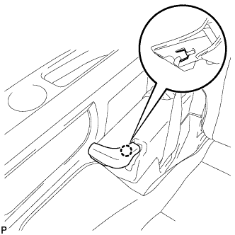
Engage the claw to install the reclining adjuster release handle.
-
-
INSTALL BACK DOOR SCUFF PLATE
-
Engage the 2 guides, 4 clips and 4 claws to install the back door scuff plate.
-
-
INSTALL BACK DOOR STRIKER COVER
-
Engage the 2 guides and 4 claws to install the back door striker cover.
-
-
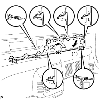
CONNECT NO. 1 SLIDE DOOR WEATHERSTRIP RH
-
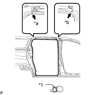
Text in Illustration *1 Alignment Mark *a Pink *b White Align the alignment marks on the weatherstrip with the protruding portions on the body indicated by the arrows in the illustration, and install the No. 1 slide door weatherstrip RH.
Note
After installation, check that the corners fit correctly.
-
-
INSTALL REAR DOOR SCUFF PLATE RH
-
Captain type rear seat:
-
Engage the 2 guides, 9 clips and 9 claws to install the rear door scuff plate RH.
-
-
Tip-up type rear seat:
-
Using the reclining lever or foot-operated walk-in pedal, tip up the rear No. 1 seat and slide it to the foremost position.
-
Engage the 5 clips, 4 claws and guide on the rear side of the scuff plate as shown in the illustration.
-
Using the slide lever, slide the rear No. 1 seat to the rearmost position.
-
Engage the 4 clips, 5 claws and guide on the front side of the scuff plate as shown in the illustration to install the rear door scuff plate RH.
-
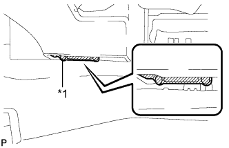
Text in Illustration *1 Protective Tape Remove the protective tape applied to the bottom of the rear seat.
-
-
-
INSTALL COOLER REFRIGERANT LIQUID PIPE D
-
Remove the attached vinyl tape from the tube.
-
Sufficiently apply compressor oil to a new O-ring and the fitting surface of the cooler refrigerant liquid pipe D.
Compressor oil ND-OIL 8 or equivalent -
Install the O-ring on the cooler refrigerant liquid pipe D.
Note
Keep the O-ring and O-ring fitting surfaces free from dirt or any foreign objects.
-
Install the cooler refrigerant liquid pipe D with the bolt.
- Torque:
- 9.8 N*m { 100 kgf*cm, 87 in.*lbf }
-
-
INSTALL COOLER REFRIGERANT SUCTION PIPE B
-
Remove the attached vinyl tape from the tube.
-
Sufficiently apply compressor oil to a new O-ring and the fitting surface of the cooler refrigerant suction pipe B.
Compressor oil ND-OIL 8 or equivalent -
Install the O-ring on the cooler refrigerant suction pipe B.
Note
Keep the O-ring and O-ring fitting surfaces free from dirt or any foreign objects.
-
Install the cooler refrigerant suction pipe B with the bolt.
- Torque:
- 9.8 N*m { 100 kgf*cm, 87 in.*lbf }
-
-
CONNECT HEATER WATER INLET HOSE B
-
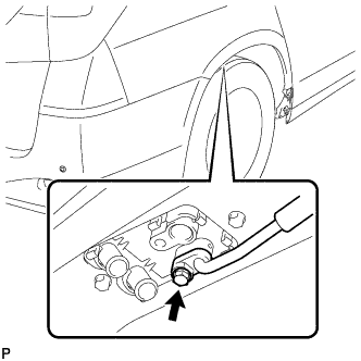
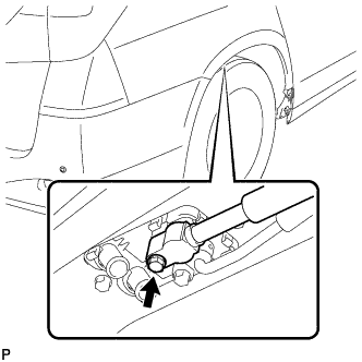
Using pliers, grip the claws of the clip and slide the clip to connect the heater water inlet hose B.
-
-
CONNECT HEATER WATER OUTLET HOSE B
-
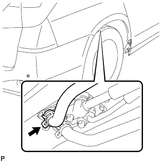
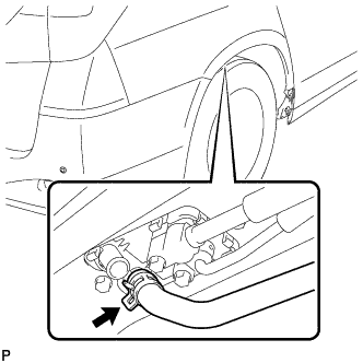
Using pliers, grip the claws of the clip and slide the clip to connect the heater water outlet hose B.
-
-
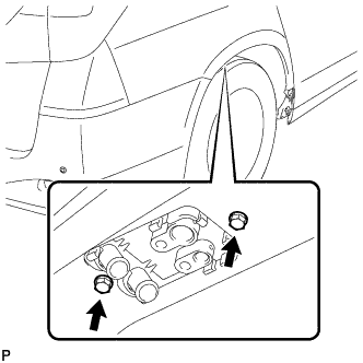
CONNECT REAR WHEEL HOUSE LINER RH
-
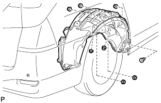
Install the 7 nuts.
-
Install a new grommet to connect the rear wheel house liner RH.
-
-
INSTALL QUARTER PANEL MUDGUARD SUB-ASSEMBLY RH (for Standard)
Use the same procedure for the RH side and LH side Click here
-
INSTALL QUARTER PANEL MUDGUARD SUB-ASSEMBLY RH (for Sport Package)
Use the same procedure for the RH side and LH side Click here
-
CHARGE WITH REFRIGERANT
-
Perform vacuum purging using a vacuum pump.
-
Charge with refrigerant HFC-134a (R134a).
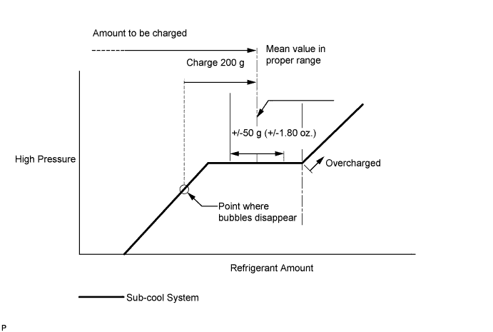
w/o No. 2 Air Conditioning Tube 780 to 880 g (27.5 to 31.0 oz.) w/ No. 2 Air Conditioning Tube 700 to 800 g (24.7 to 28.2 oz.) - SST
- 09985-20010 ( 09985-02130, 09985-02150, 09985-02090, 09985-02110, 09985-02010, 09985-02050, 09985-02060, 09985-02070, 09985-02140, 09985-02080 )
Note
-
Do not turn the A/C switch on before charging with refrigerant. Doing so will cause the compressor to work without refrigerant, resulting in overheating of the compressor.
-
Approximately 200 g (7.1 oz.) of refrigerant may need to be charged after bubbles disappear. The refrigerant amount should be checked by quantity, not with the sight glass.
Tech Tips
Ensure that sufficient refrigerant is available to recharge the system when using a refrigerant recovery unit. Refrigerant recovery units are not always able to recover 100% of the refrigerant from an A/C system.
-
-
ADD ENGINE COOLANT (for 2AZ-FE)
-
Tighten the radiator drain cock plug by hand.
-
Tighten the cylinder block drain cock plug.
- Torque:
- 13 N*m { 130 kgf*cm, 9 ft.*lbf }
-
Remove the reserve tank cap. (*1)
-
Add TOYOTA Super Long Life Coolant (SLLC).
Standard capacity 8.6 liters (9.1 US qts, 7.6 Imp. qts) Note
Never use water as a substitute for engine coolant.
Tech Tips
-
TOYOTA vehicles are filled with TOYOTA SLLC at the factory. In order to avoid damage to the engine cooling system and other technical problems, only use TOYOTA SLLC or similar high quality ethylene glycol based non-silicate, non-amine, non-nitrite, non-borate coolant with long-life hybrid organic acid technology (coolant with long-life hybrid organic acid technology is a combination of low phosphates and organic acids).
-
Squeeze the No. 1 and No. 2 radiator hoses several times. If the coolant level at the water inlet opening drops, add TOYOTA SLLC.
-
-
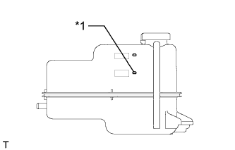
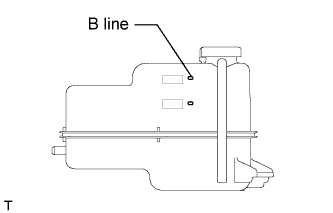
Text in Illustration *1 B Line Continue adding TOYOTA SLLC until it reaches the B line. (*2)
-
Install the reserve tank cap. (*3)
-
Run the engine at about 2000 rpm to warm it up until the thermostat opens. While the thermostat is open, circulate the coolant for several minutes. (*4)
CAUTION:
-
When pushing the radiator hoses, wear protective gloves.
-
Be careful as the radiator hoses, engine and radiator are hot.
-
Keep your hands away from the radiator fans.
Note
-
If the radiator reserve tank runs out of coolant just after the engine is started, stop the engine immediately, wait until the coolant has cooled down, and then add coolant.
-
Make sure that the reserve tank still has some coolant in it.
-
If the coolant temperature gauge indicates an excessive temperature, turn off the engine and let it cool.
-
If there is not enough coolant, the engine may overheat or be seriously damaged.
-
-
Stop the engine and wait until the coolant cools down. (*5)
-
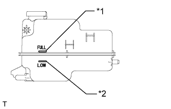
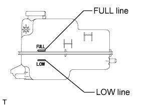
Text in Illustration *1 Full Line *2 Low Line Check that the coolant level is between the full and low lines. (*6)
Tech Tips
-
If the coolant level is below the low line, repeat steps from (*1) to (*6).
-
If the coolant level is above the full line, drain coolant so that the coolant level is between the full and low lines.
-
-
-
ADD ENGINE COOLANT (for 2GR-FE)
-
Tighten the radiator drain cock plug by hand.
-
Tighten the 2 cylinder block drain cock plugs.
- Torque:
- 13 N*m { 130 kgf*cm, 9 ft.*lbf }
-
Remove the reserve tank cap. (*1)
-
Loosen the air drain cock plug on the water inlet housing.
-
Add TOYOTA Super Long Life Coolant (SLLC).
Standard capacity 10.6 liters (11.2 US qts, 9.3 Imp. qts) Note
Never use water as a substitute for engine coolant.
Tech Tips
-
TOYOTA vehicles are filled with TOYOTA SLLC at the factory. In order to avoid damage to the engine cooling system and other technical problems, only use TOYOTA SLLC or similar high quality ethylene glycol based non-silicate, non-amine, non-nitrite, non-borate coolant with long-life hybrid organic acid technology (coolant with long-life hybrid organic acid technology consists of a combination of low phosphates and organic acids).
-
Squeeze the No. 1 and No. 2 radiator hoses several times. If the coolant level at the water inlet opening drops, add TOYOTA SLLC.
-
-
Add TOYOTA SLLC to the reserve tank until coolant overflows from the air drain cock plug hole. Then tighten the air drain cock plug on the water inlet housing.
- Torque:
- 13 N*m { 130 kgf*cm, 9 ft.*lbf }
-
Continue adding TOYOTA SLLC until it reaches the B line. (*2)
-
Install the reserve tank cap. (*3)
-
Run the engine at about 2000 rpm to warm it up until the thermostat opens. While the thermostat is open, circulate the coolant for several minutes. (*4)
CAUTION:
-
When push the radiator hoses, wear protective gloves.
-
Be careful as the radiator hoses, engine and radiator are hot.
-
Keep your hands away from the radiator fans.
Note
-
If the radiator reserve tank runs out of coolant just after the engine is started, stop the engine immediately, wait until the coolant has cooled down, and then add coolant.
-
Make sure that the reserve tank still has some coolant in it.
-
If the coolant temperature gauge indicates an excessive temperature, turn off the engine and let it cool.
-
If there is not enough coolant, the engine may overheat or be seriously damaged.
Tech Tips
-
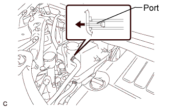
If coolant comes out from the bypass hose port connected to the reserve tank, the thermostat has been opened.
-
After the thermostat has opened, idle the engine until the coolant in the reserve tank goes from being cloudy to a clear red.
-
-
Stop the engine and wait until the coolant cools down. (*5)
-
Check that the coolant level is between the FULL and LOW lines. (*6)
Tech Tips
-
If the coolant level is below the LOW line, repeat steps from (*1) to (*6).
-
If the coolant level is above the FULL line, drain coolant so that the coolant level is between the FULL and LOW lines.
-
-
-
INSPECT FOR COOLANT LEAK (for 2AZ-FE)
-
Remove the reserve tank cap.
CAUTION:
Do not remove the reserve tank cap while the engine and radiator are still hot. Pressurized, hot engine coolant and steam may be released and cause serious burns.
-
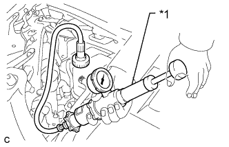
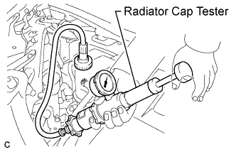
Text in Illustration *1 Radiator Cap Tester Fill the radiator and radiator reserve tank with coolant, and then attach a radiator cap tester.
-
Warm up the engine.
-
Pump the radiator cap tester to 118 kPa (1.2 kgf/cm2, 17 psi), and then check that the pressure does not drop.
If the pressure drops, check the hoses, radiator and water pump for leaks.
If there are no signs of external coolant leaks, check the heater core, cylinder block and head.
-
Reinstall the reserve tank cap.
-
-
INSPECT FOR COOLANT LEAK (for 2GR-FE)
-
Remove the radiator reservoir cap.
CAUTION:
Do not remove the radiator reservoir cap while the engine and radiator are still hot. Pressurized, hot engine coolant and steam may be released and cause serious burns.
-
Fill the radiator and reservoir with coolant, and then attach a radiator cap tester.
-
Warm up the engine.
-
Pump the radiator cap tester to 118 kPa (1.2 kgf/cm2, 17 psi), and then check that the pressure does not drop.
If the pressure drops, check the hoses, radiator and water pump for leaks.
If there are no signs of external coolant leaks, check the heater core, cylinder block and head.
-
Reinstall the radiator reservoir cap.
-
-
WARM UP ENGINE
-
Keep the A/C switch on for at least 2 minutes to warm up the compressor.
Note
Be sure to warm up the compressor when turning the A/C switch on after removing and installing the cooler refrigerant lines (including the compressor), to prevent damage to the compressor.
-
-
INSPECT FOR REFRIGERANT LEAK
-
After recharging with refrigerant, inspect for refrigerant leaks using a halogen leak detector.
-
Carry out the test under the following conditions:
-
Turn the engine switch off.
-
Secure good ventilation (the halogen leak detector may react to volatile gases which are not refrigerant, such as evaporated gasoline and exhaust gas).
-
Repeat the test 2 or 3 times.
-
Make sure that there is some refrigerant remaining in the refrigeration system.
When the compressor is off: approx. 392 to 588 kPa (4 to 6 kgf/cm2, 57 to 85 psi)
-
-
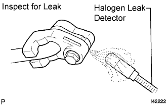
Using a halogen leak detector, inspect for refrigerant leaks from the refrigerant lines.
-
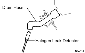
Bring the halogen leak detector close to the drain hose with the detector's power off, and then turn the detector on.
Tech Tips
-
After the blower motor has stopped, let the cooling unit stand for more than 15 minutes.
-
Bring the halogen leak detector sensor under the drain hose.
-
When bringing the halogen leak detector close to the drain hose, make sure that the halogen leak detector does not react to volatile gases. If it is not possible to avoid interference from volatile gases, the vehicle should be lifted up to allow testing.
-
-
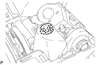
If a refrigerant leak is not detected from the drain hose, remove the blower motor control from the cooling unit. Insert the halogen leak detector sensor into the unit and perform the test.
-
Disconnect the pressure switch connector and leave it for approximately 20 minutes. Bring the halogen leak detector close to the pressure switch and perform the test.
-