- Click here
INSTALL NO. 2 AIR CONDITIONING HARNESS ASSEMBLY
-
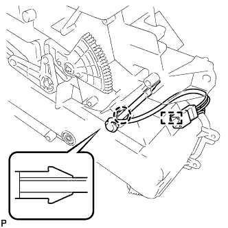
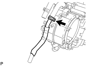
Engage the claw to install the No. 2 air conditioning harness assembly.
-
Engage the clamp to the rear cooling unit.
Tip:If the No. 2 air conditioning harness assembly is damaged during removal, replace it with a new one.
-
- Click here
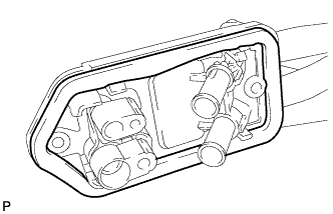
INSTALL REAR EVAPORATOR SUB-ASSEMBLY
-
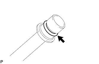
Sufficiently apply compressor oil to 2 new O-rings and the fitting surfaces.
Compressor oil ND-OIL 8 or equivalent -
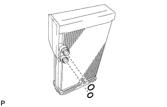
Install the 2 O-rings on the rear evaporator sub-assembly.
Note:Keep the O-rings and O-ring fitting surfaces free from dirt or any foreign objects.
-
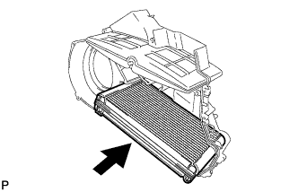
Install the rear evaporator sub-assembly as shown in the illustration.
-
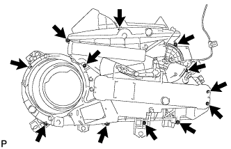
Install the 12 screws.
-
- Click here
INSTALL REAR COOLING UNIT EXPANSION VALVE
-
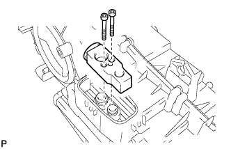
Using a 4 mm hexagon wrench, install the rear cooling unit expansion valve with the 2 hexagon bolts.
3.5 N*m 36 kgf*cm 31 in.*lbf -
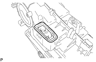
Install the grommet.
-
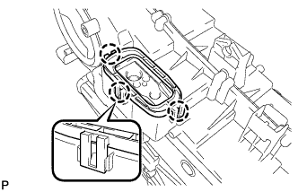
Engage the 3 claws to install the plate.
-
- Click here
INSTALL HEATER RADIATOR UNIT SUB-ASSEMBLY
-
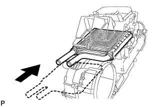
Install the heater radiator unit sub-assembly as shown in the illustration.
-
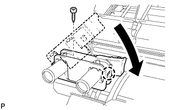
Engage the claw and install the heater radiator unit clamp.
-
Install the screw.
-
- Click here
INSTALL HEATER CLAMP
-
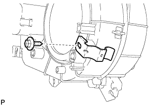
Install the heater clamp with the screw.
-
- Click here
INSTALL HEATER WATER INLET HOSE C
-
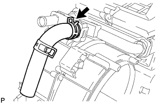
Using pliers, grip the claws of the clip and slide the clip to connect the heater water inlet hose C.
-
- Click here
INSTALL HEATER WATER OUTLET HOSE C
-
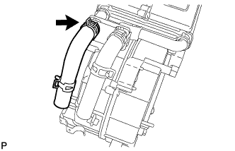
Using pliers, grip the claws of the clip and slide the clip to connect the heater water outlet hose C.
-
- Click here
INSTALL HEATER WATER INLET PIPE C
-
Using pliers, grip the claws of the clip and slide the clip to connect the heater water inlet pipe C.
-
- Click here
INSTALL HEATER WATER OUTLET PIPE C
-
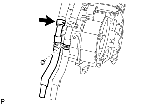
Using pliers, grip the claws of the clip and slide the clip to connect the heater water outlet pipe C.
-
Install the clamp with the screw.
-
- Click here
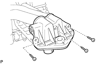
INSTALL NO. 2 HEATER COVER
-
Install the No. 2 heater cover with the 2 screws.
-
- Click here
INSTALL COOLER REFRIGERANT LIQUID PIPE E
-
Sufficiently apply compressor oil to a new O-ring and the fitting surfaces of the cooler refrigerant liquid pipe E.
Compressor oil ND-OIL 8 or equivalent -
Install the O-ring on the cooler refrigerant liquid pipe E.
Note:Keep the O-rings and O-ring fitting surfaces free from dirt or any foreign objects.
-
Install the cooler refrigerant liquid pipe E.
-
- Click here
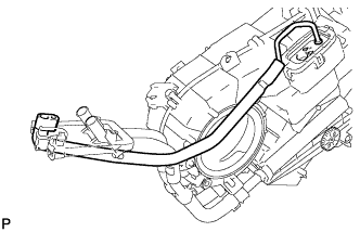
INSTALL COOLER REFRIGERANT SUCTION PIPE C
-
Sufficiently apply compressor oil to a new O-ring and the fitting surfaces of the cooler refrigerant suction pipe C.
Compressor oil ND-OIL 8 or equivalent -
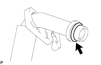
Install the O-ring on the cooler refrigerant suction pipe C.
Note:Keep the O-rings and O-ring fitting surfaces free from dirt or any foreign objects.
-
Install the cooler refrigerant suction pipe C.
-
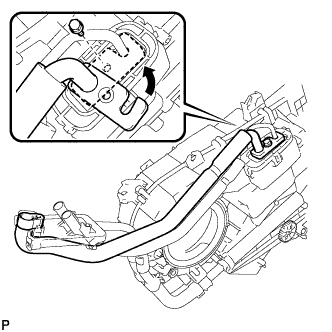
Move the hook connector in the direction indicated by the arrow in the illustration.
-
Insert the pipe joint into the fitting hole securely and tighten the bolt.
9.8 N*m 100 kgf*cm 87 in.*lbf -
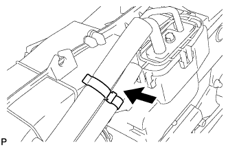
Engage the piping clamp.
-
Install a new No. 1 cooler packing.
-
- Click here
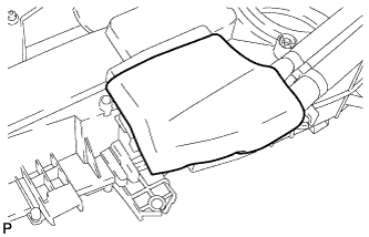
INSTALL NO. 1 HEATER COVER
-
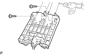
Install the No. 1 heater cover with the 3 screws.
-
Install a new No. 2 cooler packing.
-
- Click here
INSTALL DRAIN COOLER HOSE
-
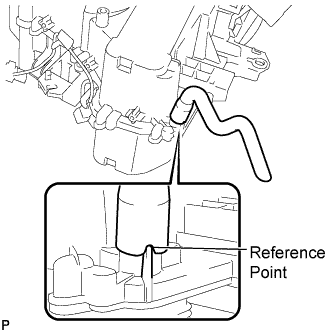
Using the reference point, install the drain cooler hose.
-
- Click here
INSTALL BLOWER MOTOR CONTROLLER
-
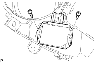
Install the blower motor controller with the 2 screws.
-
- Click here
INSTALL REAR BLOWER MOTOR SUB-ASSEMBLY
-
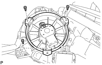
Install the rear blower motor sub-assembly with the 3 screws.
-
- Click here
INSTALL HEATER BRACKET
-
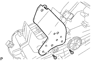
Install the heater bracket with the 2 screws.
-
- Click here
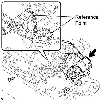
INSTALL REAR AIR OUTLET CONTROL SERVO MOTOR SUB-ASSEMBLY
-
Using the reference points, install the rear air outlet control servo motor sub-assembly with the 2 screws.
-
Connect the connector.
-
- Click here
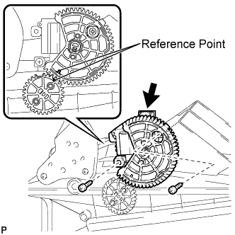
INSTALL REAR AIR MIX CONTROL SERVO MOTOR SUB-ASSEMBLY
-
Using the reference points, install the rear air mix control servo motor sub-assembly with the 2 screws.
-
Connect the connector.
-
- Click here
INSTALL REAR SIDE NO. 3 AIR DUCT
-
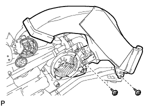
Install the rear side No. 3 air duct with the 2 screws.
-