REAR AIR CONDITIONING UNIT REMOVAL

Tech Tips
Adjust the air outlet mode setting to FOOT.
-
RECOVER REFRIGERANT FROM REFRIGERATION SYSTEM
-
Start up the engine.
-
Turn the A/C switch on.
-
Operate the cooler compressor at an engine speed of approximately 1000 rpm for 5 to 6 minutes to circulate the refrigerant. This causes most of the compressor oil from the various components of the A/C system to collect in the A/C compressor.
-
Stop the engine.
-
Recover the refrigerant from the A/C system using a refrigerant recovery unit.
-
-
REMOVE QUARTER PANEL MUDGUARD SUB-ASSEMBLY RH (for Standard)
Use the same procedure for the RH side and LH side Click here
-
REMOVE QUARTER PANEL MUDGUARD SUB-ASSEMBLY RH (for Sport Package)
Use the same procedure for the RH side and LH side Click here
-
DISCONNECT REAR WHEEL HOUSE LINER RH
-
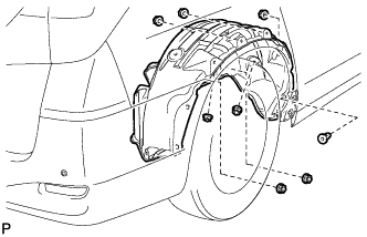
Remove the 7 nuts.
-
Remove the grommet and disconnect the rear wheel house liner RH.
-
-
DISCONNECT HEATER WATER OUTLET HOSE B
-
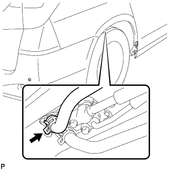
Using pliers, grip the claws of the clip and slide the clip to disconnect the heater water outlet hose B.
Note
-
Do not apply excessive force to the heater water outlet hose B.
-
Prepare a drain pan or cloth in case the coolant leaks.
-
-
-
DISCONNECT HEATER WATER INLET HOSE B
-
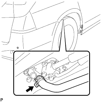
Using pliers, grip the claws of the clip and slide the clip to disconnect the heater water inlet hose B.
Note
-
Do not apply excessive force to the heater water inlet hose B.
-
Prepare a drain pan or cloth in case the coolant leaks.
-
-
-
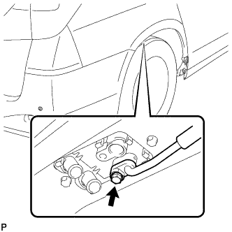
DISCONNECT COOLER REFRIGERANT SUCTION PIPE B
-
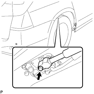
Remove the bolt and disconnect the cooler refrigerant suction pipe B.
-
Remove the O-ring from the cooler refrigerant suction pipe B.
Note
Seal the openings of the disconnected parts using vinyl tape to prevent entry of moisture and foreign matter.
-
-
DISCONNECT COOLER REFRIGERANT LIQUID PIPE D
-
Remove the bolt and disconnect the cooler refrigerant liquid pipe D.
-
Remove the O-ring from the cooler refrigerant liquid pipe D.
Note
Seal the openings of the disconnected parts using vinyl tape to prevent entry of moisture and foreign matter.
-
-
REMOVE REAR DOOR SCUFF PLATE RH
-
Captain type rear seat:
-
Disengage the 9 claws, 9 clips and 2 guides, and remove the rear door scuff plate RH.
-
-
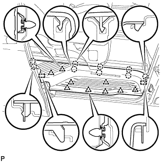
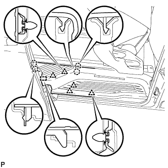
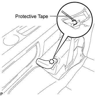
Tip-up type rear seat:
-
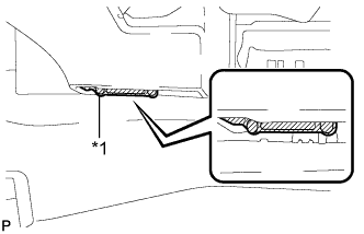
Text in Illustration *1 Protective Tape Apply protective tape to the bottom of the seat as shown in the illustration.
-
Using the slide lever, slide the rear No. 1 seat to the rearmost position.
-
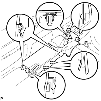
Disengage the 4 clips, 5 claws and guide on the front side of the scuff plate as shown in the illustration.
Note
To prevent damage to the scuff plate, make sure not to use excessive force when disengaging the clips, claws and guide.
-
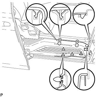
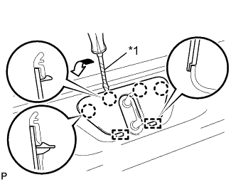
Using the reclining lever or foot-operated walk-in pedal, tip up the rear No. 1 seat and slide it to the foremost position.
-
Disengage the 5 clips, 4 claws and guide on the rear side of the scuff plate as shown in the illustration, and remove the rear door scuff plate RH.
Note
To prevent damage to the scuff plate, make sure not to use excessive force when disengaging the clips, claws and guide.
-
-
-
DISCONNECT NO. 1 SLIDE DOOR WEATHERSTRIP RH
-
REMOVE BACK DOOR STRIKER COVER
-
Text in Illustration *1 Protective Tape Using a screwdriver, disengage the 4 claws and 2 guides, and remove the back door striker cover.
Tech Tips
Tape the screwdriver tip before use.
-
-
REMOVE BACK DOOR SCUFF PLATE
-
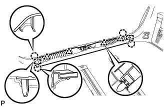
Remove the 4 claws, 4 clips and 2 guides, and remove the back door scuff plate.
-
-
ADJUST REAR NO. 2 SEAT ASSEMBLY RH
-
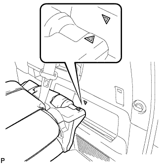
Adjust the rear No. 2 seat assembly so that the positioning marks are aligned as shown in the illustration.
-
-
REMOVE RECLINING ADJUSTER RELEASE HANDLE RH
-
Using a screwdriver wrapped with protective tape, disengage the claw and remove the reclining adjuster release handle.
-
-
REMOVE UPPER SEAT TRACK RAIL COVER RH
-
Disengage the 5 claws and clip.
-
Disengage the 2 guides and remove the upper seat track rail cover.
-
Disengage the 2 claws and remove the grommet.
-
-
REMOVE NO. 1 SEAT TRACK LOCK PLATE COVER (for RH Side)
-
Disengage the 2 claws, guide and remove the No. 1 seat track lock plate cover.
-
-
REMOVE REAR NO. 2 SEAT ASSEMBLY RH
-
Install the 2 stopper bolts in the order of <B>, <A>.
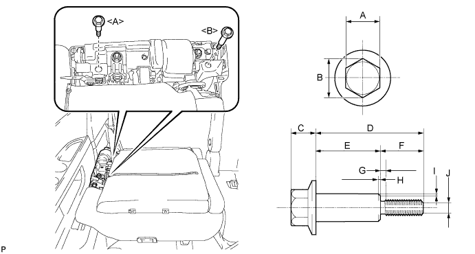
- Torque:
- 21 N*m { 214 kgf*cm, 16 ft.*lbf }
Note
Use service stopper bolts with part numbers 72702-58120 and 72702-58110, or other bolts of an equivalent size (M8 X 1.25).
Tech Tips
Stopper bolts sizes are as shown below.
Recommended Stopper Bolt Part Length A 14 mm (0.551 in.) B 15.5 mm (0.610 in.) or more C 10 mm (0.394 in.) or less D 72702-58110 Bolt <A> 45.7 mm (1.80 in.) 72702-58120 Bolt <B> 61.2 mm (2.41 in.) E 72702-58110 Bolt <A> 27.7 mm (1.09 in.) 72702-58120 Bolt <B> 48.2 mm (1.90 in.) F 18 mm (0.709 in.) G 2.5 mm (0.0984 in.) or less H 1.0 mm (0.0394 in.) or less I 0.75 mm (0.0295 in.) or less J 5.5 mm (0.217 in.) -
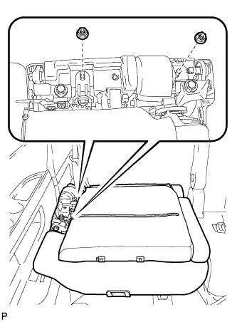
Remove the 2 nuts and disconnect the rear No. 2 seat outer belt assembly.
-
Remove the rear No. 2 seat assembly.
Note
Do not damage the rear No. 2 seat assembly, body or body interior.
-
-
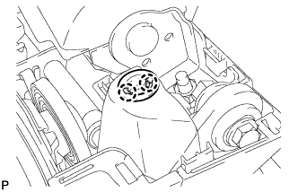
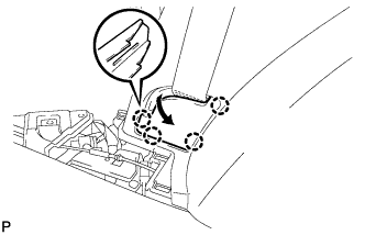
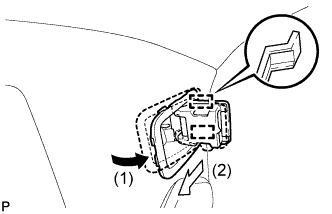
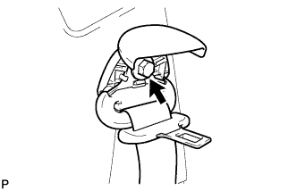
REMOVE NO. 1 LUGGAGE COMPARTMENT TRIM HOOK
-
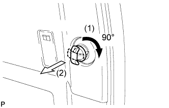
Turn the No. 1 luggage compartment trim hook clockwise approximately 90° and pull it out as shown in the illustration.
-
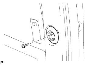
Remove the bolt and No. 1 luggage compartment trim hook.
-
-
REMOVE ROPE HOOK ASSEMBLY (for RH Side)
-
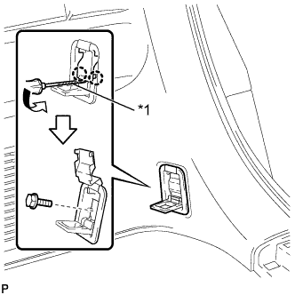
Text in Illustration *1 Protective Tape Using a screwdriver, disengage the 2 claws.
Tech Tips
Tape the screwdriver tip before use.
-
Remove the bolt and the rope hook assembly.
-
-
REMOVE INNER LUGGAGE COMPARTMENT TRIM COVER RH (for 60/40 Split Seat Type)
-
Disengage the 4 claws and remove the inner luggage compartment trim cover RH as shown in the illustration.
-
-
DISCONNECT REAR NO. 1 SEAT OUTER BELT ASSEMBLY RH (for 60/40 Split Seat Type)
-
Remove the bolt and disconnect the floor end of the rear No. 1 seat outer belt assembly.
-
-
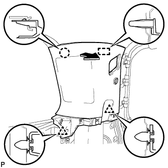
REMOVE DECK SIDE GARNISH RH
-
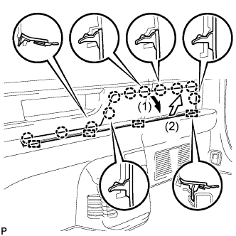
Disengage the 11 claws and 4 guides, and remove the deck side garnish RH as shown in the illustration.
-
-
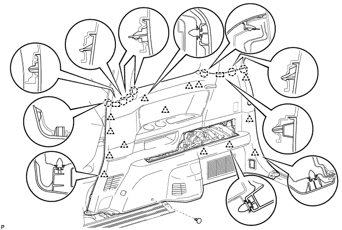
REMOVE REAR QUARTER TRIM PANEL ASSEMBLY RH
-
Remove the clip.
-
Disengage the 14 clips, 7 claws and 2 guides.
-
Disconnect the connectors, and remove the rear quarter trim panel assembly RH.
-
-
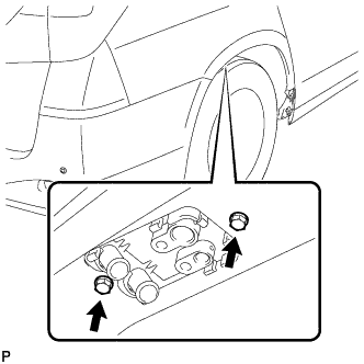
REMOVE REAR SEAT HOOK SUB-ASSEMBLY RH
-

Remove the 2 bolts.
-
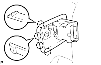
Disengage the 4 claws.
-
Disengage the 2 guides and remove the rear seat hook sub-assembly RH as shown in the illustration.
-
-
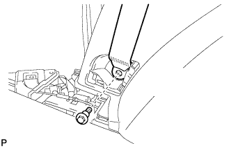
DISCONNECT REAR NO. 2 SEAT OUTER BELT ASSEMBLY RH
-
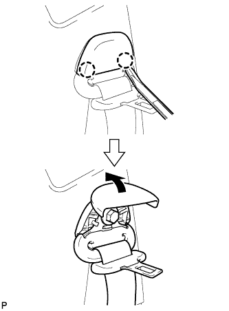
Using a moulding remover, disengage the 2 claws and open the cover.
-
Loosen the bolt and disconnect the shoulder anchor of the rear No. 2 seat outer belt assembly.
-
-
REMOVE UPPER ROOF SIDE INNER GARNISH RH
-
Disengage the 2 clips, claw and guide, and remove the upper roof side inner garnish RH as shown in the illustration.
-
-
REMOVE REAR NO. 2 SEAT TRACK ASSEMBLY RH
-
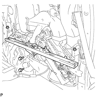
Remove the 2 bolts, 2 nuts and the rear No. 2 seat track assembly RH.
-
-
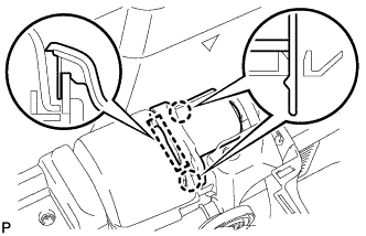
REMOVE NO. 1 COOLER AIR DUCT
-
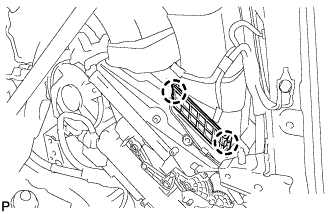
Disengage the 2 claws and remove the cooler plate.
-
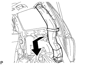
Remove the No. 1 cooler air duct as shown in the illustration.
-
-
REMOVE DOOR CONTROL RECEIVER
-
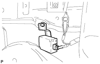
Disconnect the connector.
-
Remove the bolt and door control receiver.
-
-
REMOVE REAR COOLING UNIT ASSEMBLY
-
Remove the 2 bolts.
-
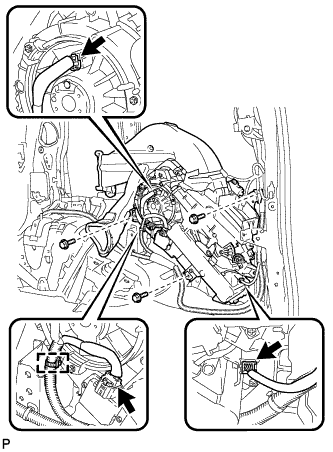
Disengage the clamp.
-
Disconnect each connector.
-
Remove the 3 bolts and the rear cooling unit assembly.
-