SEAT BELT WARNING SYSTEM TERMINALS OF ECU

-
COMBINATION METER ASSEMBLY
-
Disconnect the G19 combination meter assembly connector.

-
Measure the resistance according to the value(s) in the table below.
Tech Tips
Measure the values on the wire harness side with connector disconnected.
Tester Connection Wiring Color Terminal Description Condition Specified Condition G19-9 (P/SB) - Body ground G - Body ground*1
Y - Body ground*2
Front passenger seat belt buckle switch signal Front passenger seat occupied, seat belt fastened 10 kΩ or higher G19-9 (P/SB) - Body ground G - Body ground*1
Y - Body ground*2
Front passenger seat belt buckle switch signal Front passenger seat occupied, seat belt unfastened Below 1 Ω G19-3 (EP) - Body ground BR - Body ground Ground Always Below 1 Ω
-
*1: for RHD
-
*2: for LHD
If the result is not as specified, there may be a malfunction in the wire harness.
-
-
Reconnect the G19 combination meter assembly connector.
-
Measure the voltage according to the value(s) in the table below.
Tester Connection Wiring Color Terminal Description Condition Specified Condition G19-1 (IG2) - Body ground G - Body ground Engine switch power supply Engine switch off Below 1 V G19-1 (IG2) - Body ground G - Body ground Engine switch power supply Engine switch on (IG) 11 to 14 V G19-10 (PBLT) - Body ground SB - Body ground Front passenger seat belt warning light signal Engine switch on (IG), front passenger seat occupied, seat belt fastened 11 to 14 V G19-10 (PBLT) - Body ground SB - Body ground Front passenger seat belt warning light signal Engine switch on (IG), front passenger seat occupied, seat belt unfastened Below 1 V If the result is not as specified, the combination meter assembly may have a malfunction.
-
-
AIR CONDITIONING CONTROL ASSEMBLY
-
Disconnect the G26 air conditioning control assembly connector.

-
Measure the resistance according to the value(s) in the table below.
Tech Tips
Measure the values on the wire harness side with connector disconnected.
Tester Connection Wiring Color Terminal Description Condition Specified Condition G26-7 (LAPL) - Body ground SB - Body ground Front passenger seat belt warning light signal Front passenger seat occupied, seat belt fastened 10 kΩ or higher G26-7 (LAPL) - Body ground SB - Body ground Front passenger seat belt warning light signal Front passenger seat occupied, seat belt unfastened Below 1 Ω If the result is not as specified, there may be a malfunction in the wire harness.
-
Reconnect the G26 air conditioning control assembly connector.
-
Measure the voltage according to the value(s) in the table below.
Tester Connection Wiring Color Terminal Description Condition Specified Condition G26-5 (IG+) - Body ground R - Body ground Engine switch power supply Engine switch off Below 1 V G26-5 (IG+) - Body ground R - Body ground Engine switch power supply Engine switch on (IG) 11 to 14 V If the result is not as specified, the air conditioning control assembly may have a malfunction.
-
-
MAIN BODY ECU
-
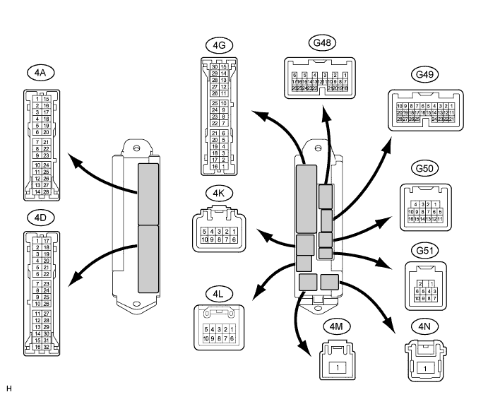
Disconnect the 4A and 4K main body ECU connectors.
-
Disconnect the G48 and G50 main body ECU connectors.
-
Measure the resistance and voltage according to the value(s) in the table below.
Tech Tips
Measure the values on the wire harness side with connector disconnected.
Tester Connection Wiring Color Terminal Description Condition Specified Condition 4K-1 (BECU) - Body ground R - Body ground Battery power supply Always 11 to 14 V 4K-9 (BATB) - Body ground W - Body ground Battery power supply Always 11 to 14 V 4A-26 (ACC) - Body ground GR - Body ground ACC power supply Engine switch off Below 1 V 4A-26 (ACC) - Body ground GR - Body ground ACC power supply Engine switch on (ACC) 11 to 14 V G50-1 (GND) - Body ground W-B - Body ground Ground Always Below 1 Ω 4A-3 (GND2) - Body ground W-B - Body ground Ground Always Below 1 Ω G48-7 (DBKL) - Body ground Y - Body ground Driver seat belt buckle switch signal Driver seat belt fastened 10 kΩ or higher G48-7 (DBKL) - Body ground Y - Body ground Driver seat belt buckle switch signal Driver seat belt unfastened Below 1 Ω If the result is not as specified, there may be a malfunction in the wire harness.
-