SEAT RAIL REMOVAL

-
REMOVE REAR SEAT HEADREST ASSEMBLY (for Manual Seat)
-
REMOVE REAR SEAT LOWER CUSHION SHIELD RH (for Manual Seat)
-
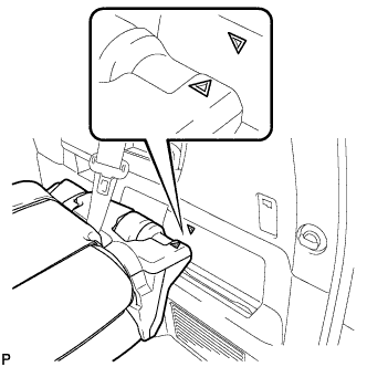
Operate the rear seat lock control lever and move the ottoman to the foremost position.
-
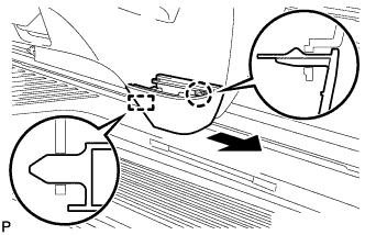
Disengage the claw.
-
Disengage the guide and remove the rear seat lower cushion shield as shown in the illustration.
-
-
REMOVE REAR NO. 1 SEAT ASSEMBLY RH (for Manual Seat)
-
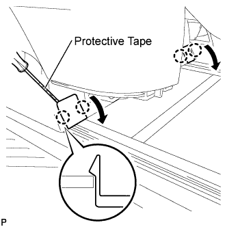
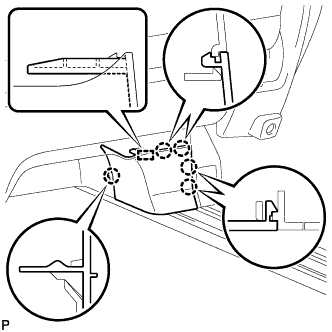
Using a screwdriver wrapped with protective tape, disengage the 4 claws and open the 2 covers.
-
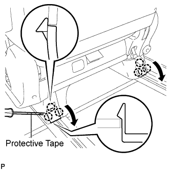
Using a screwdriver wrapped with protective tape, disengage the 6 claws and open the 2 covers.
-
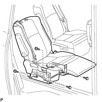
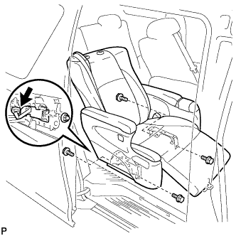
Remove the 4 bolts.
-
Remove the rear No. 1 seat assembly.
Note
Be careful not to damage the vehicle body.
-
-
REMOVE REAR SEAT HEADREST ASSEMBLY (for Manual Seat)
-
REMOVE REAR SEAT LOWER CUSHION SHIELD LH (for Manual Seat)
Tech Tips
Use the same procedure for the RH side and LH side Click here.
-
REMOVE REAR NO. 1 SEAT ASSEMBLY LH (for Manual Seat)
Tech Tips
Use the same procedure for the RH side and LH side Click here.
-
REMOVE REAR SEAT HEADREST ASSEMBLY (for Power Seat)
-
REMOVE REAR SEAT LOWER CUSHION SHIELD RH (for Power Seat)
-
Disengage the claw and the guide and remove the rear seat lower cushion shield as shown in the illustration.
-
-
REMOVE REAR SEAT LEG COVER RH (for Power Seat)
-
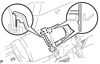
Disengage the 5 claws and the guide and remove the rear seat leg cover.
-
-
REMOVE REAR NO. 1 SEAT ASSEMBLY RH (for Power Seat)
-
Operate the ottoman switch to fully raise the ottoman.
-
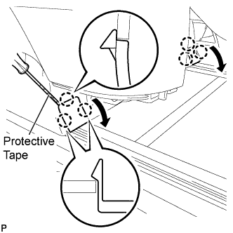
Using a screwdriver wrapped with protective tape, disengage the 6 claws and open the 2 covers as shown in the illustration.
-
Using a screwdriver wrapped with protective tape, disengage the 6 claws and open the 2 covers as shown in the illustration.
-
Operate the power seat switch and move the seatback to the fully folded position.
-
Remove the 4 bolts.
-
Remove the nut and disconnect the wiring harness protector set.
-
Disconnect each connector.
-
Remove the rear No. 1 seat assembly.
Note
Be careful not to damage the vehicle body.
-
-
REMOVE REAR SEAT HEADREST ASSEMBLY (for Power Seat)
-
REMOVE REAR SEAT LOWER CUSHION SHIELD LH (for Power Seat)
Tech Tips
Use the same procedure for the RH side and LH side Click here.
-
REMOVE NO. 2 SEAT LEG COVER LH (for Power Seat)
Tech Tips
Use the same procedure for the RH side and LH side Click here.
-
REMOVE REAR NO. 1 SEAT ASSEMBLY LH (for Power Seat)
Tech Tips
Use the same procedure for the RH side and LH side Click here.
-
ADJUST REAR NO. 2 SEAT ASSEMBLY RH
-
Adjust the rear No. 2 seat assembly so that the positioning marks are aligned as shown in the illustration.
-
-
REMOVE RECLINING ADJUSTER RELEASE HANDLE RH
-
Using a screwdriver wrapped with protective tape, disengage the claw and remove the reclining adjuster release handle.
-
-
REMOVE UPPER SEAT TRACK RAIL COVER RH
-
Disengage the 5 claws and clip.
-
Disengage the 2 guides and remove the upper seat track rail cover.
-
Disengage the 2 claws and remove the grommet.
-
-
REMOVE NO. 1 SEAT TRACK LOCK PLATE COVER
-
Disengage the 2 claws, guide and remove the No. 1 seat track lock plate cover.
-
-
REMOVE NO. 2 SEAT HEADREST ASSEMBLY
-
REMOVE REAR NO. 2 SEAT ASSEMBLY RH
-
Install the 2 stopper bolts in the order of <B>, <A>.
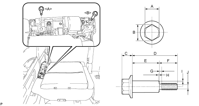
- Torque:
- 21 N*m { 214 kgf*cm, 16 ft.*lbf }
Note
Use service stopper bolts with part numbers 72702-58120 and 72702-58110, or other bolts of an equivalent size (M8 X 1.25).
Tech Tips
Stopper bolts sizes are as shown below.
Recommended Stopper Bolt Part Length A 14 mm (0.551 in.) B 15.5 mm (0.610 in.) or more C 10 mm (0.394 in.) or less D 72702-58110 Bolt <A> 45.7 mm (1.80 in.) 72702-58120 Bolt <B> 61.2 mm (2.41 in.) E 72702-58110 Bolt <A> 27.7 mm (1.09 in.) 72702-58120 Bolt <B> 48.2 mm (1.90 in.) F 18 mm (0.709 in.) G 2.5 mm (0.0984 in.) or less H 1.0 mm (0.0394 in.) or less I 0.75 mm (0.0295 in.) or less J 5.5 mm (0.217 in.) -
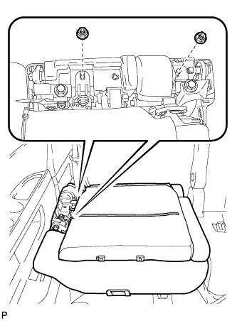
Remove the 2 nuts and disconnect the rear No. 2 seat outer belt assembly.
-
Remove the rear No. 2 seat assembly.
Note
Do not damage the rear No. 2 seat assembly, body or body interior.
-
-
ADJUST REAR NO. 2 SEAT ASSEMBLY LH
Tech Tips
Use the same procedure for the RH side and LH side Click here.
-
REMOVE RECLINING ADJUSTER RELEASE HANDLE LH
Tech Tips
Use the same procedure for the RH side and LH side Click here.
-
REMOVE UPPER SEAT TRACK RAIL COVER LH
Tech Tips
Use the same procedure for the RH side and LH side Click here.
-
REMOVE NO. 1 SEAT TRACK LOCK PLATE COVER
Tech Tips
Use the same procedure for the RH side and LH side Click here.
-
REMOVE NO. 2 SEAT HEADREST ASSEMBLY
-
REMOVE REAR SEAT HEADREST ASSEMBLY
-
REMOVE REAR NO. 2 SEAT ASSEMBLY LH
Tech Tips
Use the same procedure for the RH side and LH side Click here.
-
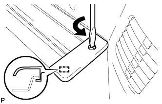
REMOVE NO. 1 LUGGAGE COMPARTMENT TRIM HOOK
-
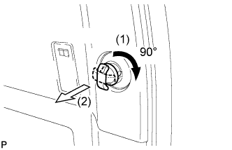
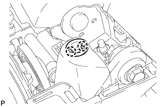
Turn the No. 1 luggage compartment trim hook clockwise approximately 90° and pull it out as shown in the illustration.
-
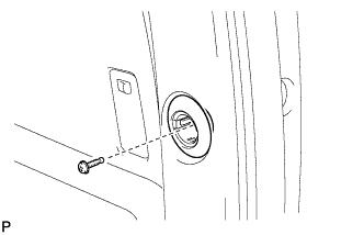
Remove the bolt and No. 1 luggage compartment trim hook.
-
-
REMOVE ROPE HOOK ASSEMBLY (for RH Side)
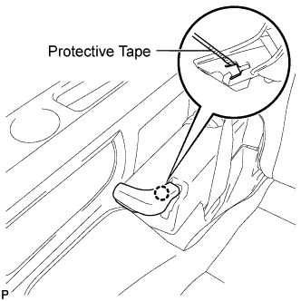
-
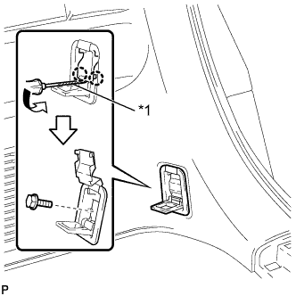
Text in Illustration *1 Protective Tape Using a screwdriver, disengage the 2 claws.
Tech Tips
Tape the screwdriver tip before use.
-
Remove the bolt and the rope hook assembly.
-
-
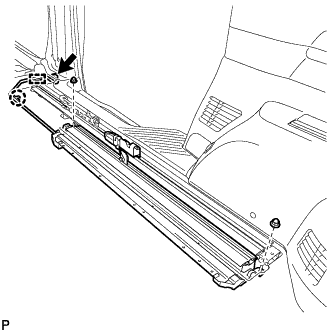
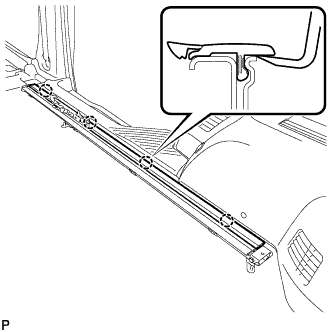
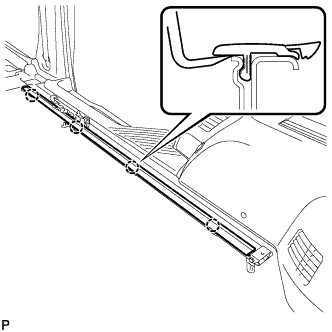
REMOVE DECK SIDE GARNISH RH
-
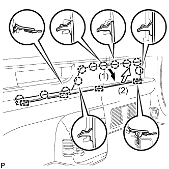
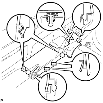
Disengage the 11 claws and 4 guides, and remove the deck side garnish RH as shown in the illustration.
-
-
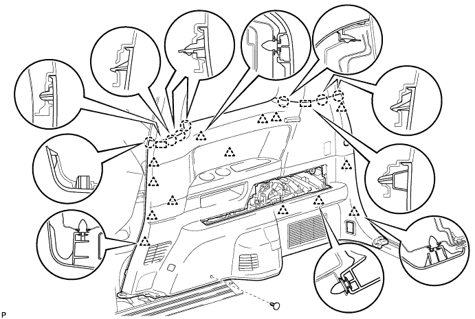
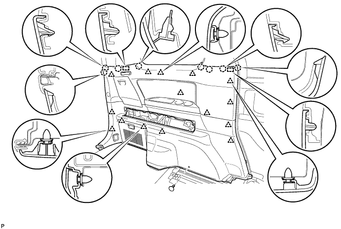
REMOVE REAR QUARTER TRIM PANEL ASSEMBLY RH
-
Remove the clip.
-
Disengage the 14 clips, 7 claws and 2 guides.
-
Disconnect the connectors, and remove the rear quarter trim panel assembly RH.
-
-
REMOVE NO. 2 LUGGAGE COMPARTMENT TRIM HOOK
Tech Tips
Use the same procedure for the No. 2 luggage compartment trim hook and No. 1 luggage compartment trim hook.
-
REMOVE ROPE HOOK ASSEMBLY (for LH Side)
Tech Tips
Use the same procedure for the LH side and RH side.
-
REMOVE DECK SIDE GARNISH LH
-
Disengage the 12 claws and 4 guides, and remove the deck side garnish LH as shown in the illustration.
-
-
REMOVE REAR QUARTER TRIM PANEL ASSEMBLY LH
-
Remove the clip.
-
Disengage the 15 clips, 8 claws and 2 guides, and remove the rear quarter trim panel assembly LH.
-
-
REMOVE REAR NO. 2 SEAT TRACK ASSEMBLY RH
-
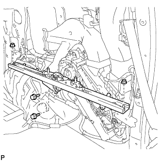
Remove the 2 bolts, 2 nuts and the rear No. 2 seat track assembly RH.
-
-
REMOVE REAR NO. 2 SEAT TRACK ASSEMBLY LH
Tech Tips
Use the same procedure for the RH side and LH side.
-
REMOVE REAR SEAT TRACK SLIDE STOPPER
-
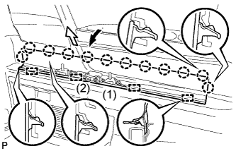
REMOVE REAR SEAT LOCK STRIKER COVER
-
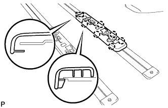
Disengage the 7 claws and guide, and remove the rear seat lock striker cover.
Tech Tips
Use the same procedure for the RH side and LH side.
-
-
REMOVE NO. 3 FLOOR CARPET MOULDING (for Manual Seat)
-
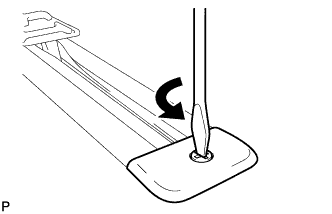
Using a screwdriver, turn the clip 90° counterclockwise to release the lock, and remove the No. 3 floor carpet moulding.
Tech Tips
Use the same procedure for the other 7 mouldings.
-
-
REMOVE NO. 3 FLOOR CARPET MOULDING (for Power Seat)
-
For mouldings those other than installed on the rear outer sides of the vehicle:
-
Using a screwdriver, turn the clip 90° counterclockwise to release the lock, and remove the No. 3 floor carpet moulding.
Tech Tips
Use the same procedure for the other 7 mouldings.
-
-
For mouldings installed on the rear outer sides of the vehicle:
-
Using a screwdriver, turn the clip 90° counterclockwise to release the lock.
-
Disengage the guide and remove the No. 3 floor carpet moulding.
Tech Tips
Use the same procedure for the RH side and LH side.
-
-
-
REMOVE WIRING HARNESS PROTECTOR SET (for Power Seat)
-
Disconnect the connector.
-
Disengage the claw and clamp.
-
Remove the 2 nuts and the wiring harness protector set.
-
-
REMOVE WIRING HARNESS PROTECTOR SET (for Power Seat)
Tech Tips
Use the same procedure for the RH side and LH side.
-
REMOVE NO. 1 SEAT TRACK LOWER RAIL PROTECTOR
-
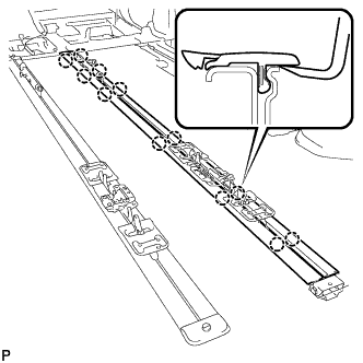
Using a moulding remover, disengage the 4 claws and remove the No. 1 seat track lower rail protector.
Tech Tips
Use the same procedure for the RH side and LH side.
-
-
REMOVE NO. 2 SEAT TRACK LOWER RAIL PROTECTOR
-
Using a moulding remover, disengage the 4 claws and remove the No. 2 seat track lower rail protector.
Tech Tips
Use the same procedure for the RH side and LH side.
-
-
REMOVE NO. 3 SEAT TRACK LOWER RAIL PROTECTOR
-
Using a moulding remover, disengage the 12 claws and remove the 2 No. 3 seat track lower rail protectors.
Tech Tips
Use the same procedure for the RH side and LH side.
-
-
REMOVE FUEL TANK ASSEMBLY
-
Remove the fuel tank assembly Click here.
-
-
REMOVE FRONT FLOOR NO. 2 HEAT INSULATOR
-
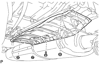
Remove the bolt and 3 nuts, and remove the front floor No. 2 heat insulator.
-
-
DISCONNECT HEATER CLAMP (for Front Side)
-
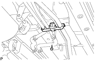
Remove the bolt and disconnect the heater clamp.
-
-
DISCONNECT HEATER CLAMP (for Rear Side)
-
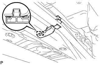
Disengage the clamp and disconnect the heater clamp.
-
-
REMOVE REAR SEAT OUTER TRACK ASSEMBLY RH
-
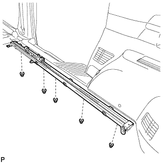
Remove the 5 nuts from the bottom of the vehicle and remove the rear seat outer track assembly RH.
-
-
REMOVE REAR SEAT OUTER TRACK ASSEMBLY LH
Tech Tips
Use the same procedure for the RH side and LH side.
-
REMOVE REAR SEAT INNER TRACK ASSEMBLY RH
-
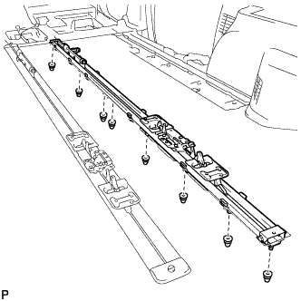
Remove the 8 nuts from the bottom of the vehicle and remove the rear seat inner track assembly RH.
-
-
REMOVE REAR SEAT INNER TRACK ASSEMBLY LH
Tech Tips
Use the same procedure for the RH side and LH side.