REAR NO. 2 SEAT ASSEMBLY REMOVAL

-
ADJUST REAR NO. 2 SEAT ASSEMBLY
-
Adjust the rear No. 2 seat assembly so that the positioning marks are aligned as shown in the illustration.
-
-
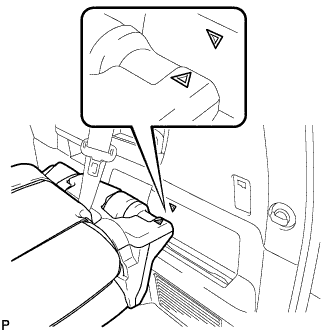
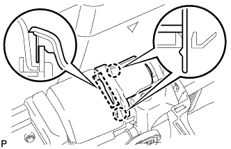
REMOVE RECLINING ADJUSTER RELEASE HANDLE
-
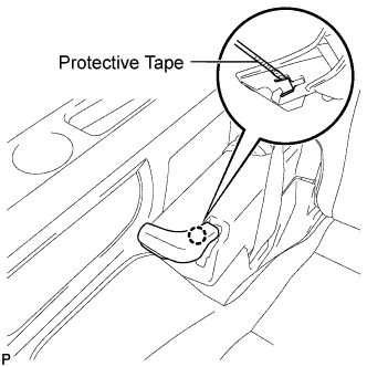
Using a screwdriver wrapped with protective tape, disengage the claw and remove the reclining adjuster release handle.
-
-
REMOVE UPPER SEAT TRACK RAIL COVER
-
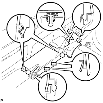
Disengage the 5 claws and clip.
-
Disengage the 2 guides and remove the upper seat track rail cover.
-
Disengage the 2 claws and remove the grommet.
-
-
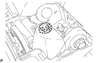
REMOVE NO. 1 SEAT TRACK LOCK PLATE COVER
-
Disengage the 2 claws, guide and remove the No. 1 seat track lock plate cover.
-
-
REMOVE NO. 2 SEAT HEADREST ASSEMBLY
-
REMOVE REAR SEAT HEADREST ASSEMBLY (for LH Side)
-
REMOVE REAR NO. 2 SEAT ASSEMBLY
-
Install the 2 stopper bolts in the order of <B>, <A>.
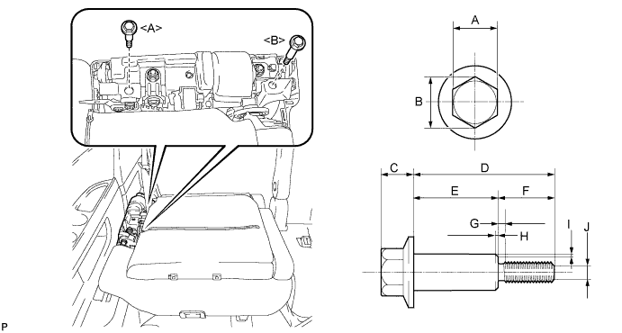
- Torque:
- 21 N*m { 214 kgf*cm, 16 ft.*lbf }
Note
Use service stopper bolts with part numbers 72702-58120 and 72702-58110, or other bolts of an equivalent size (M8 X 1.25).
Tech Tips
Stopper bolts sizes are as shown below.
Recommended Stopper Bolt Part Length A 14 mm (0.551 in.) B 15.5 mm (0.610 in.) or more C 10 mm (0.394 in.) or less D 72702-58110 Bolt <A> 45.7 mm (1.80 in.) 72702-58120 Bolt <B> 61.2 mm (2.41 in.) E 72702-58110 Bolt <A> 27.7 mm (1.09 in.) 72702-58120 Bolt <B> 48.2 mm (1.90 in.) F 18 mm (0.709 in.) G 2.5 mm (0.0984 in.) or less H 1.0 mm (0.0394 in.) or less I 0.75 mm (0.0295 in.) or less J 5.5 mm (0.217 in.) -
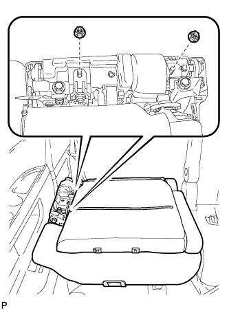
Remove the 2 nuts and disconnect the rear No. 2 seat outer belt assembly.
-
Remove the rear No. 2 seat assembly.
Note
Do not damage the rear No. 2 seat assembly, body or body interior.
-