DESCRIPTION
When the SET switch and a seat memory switch (M1 switch, M2 switch or M3 switch) are pressed simultaneously, the outer mirror control ECU assembly commands the position control ECU and switch assembly through CAN communication to record each position value.
The position control ECU and seat adjustment switches are built into an assembly that is referred to as the position control ECU and switch assembly.
INSPECTION PROCEDURE
-
The seat position will not be recorded if the SET switch and 2 or more of the seat memory switches (for example, M1 switch and M2 switch) are pressed simultaneously.
-
If a memorizing operation has failed, release all switches. The seat memory function does not operate unless the switches are released.
PROCEDURE
- Click here
CHECK CAN COMMUNICATION SYSTEM
-
Use the intelligent tester to check if the CAN communication system is functioning normally (Click here).
OK CAN communication DTC is not output.
- OKClick here
- NGClick here
-
- Click here
CHECK POWER SEAT CONTROL FUNCTION (USING POSITION CONTROL ECU AND SWITCH ASSEMBLY)
-
Check that each function of the power seat operates normally by using the position control ECU and switch assembly.
OK Each function of power seat operates normally by using position control ECU and switch assembly.
- OKClick here
- NGClick here
-
- Click here
READ VALUE USING INTELLIGENT TESTER (SEAT MEMORY SWITCH)
-
Connect the intelligent tester to the DLC3.
-
Turn the engine switch on (IG).
-
Turn the intelligent tester on.
-
Enter the following menus: Body / D-Seat / Data List
-
Read the Data List according to the display on the intelligent tester.
Table 1. D-Seat Tester Display Measurement Item/Range Normal Condition Diagnostic Note SET Switch SET switch signal / ON or OFF ON: SET switch on
OFF: SET switch off
- M1 Switch M1 switch signal / ON or OFF ON: M1 switch on
OFF: M1 switch off
- M2 Switch M2 switch signal / ON or OFF ON: M2 switch on
OFF: M2 switch off
- M3 Switch M3 switch signal / ON or OFF ON: M3 switch on
OFF: M3 switch off
- OK ON or OFF is displayed on the intelligent tester according to the table above.
- OKClick here
- NGClick here
-
- Click here
READ VALUE USING INTELLIGENT TESTER (P SIGNAL)
-
Read the Data List according to the display on the intelligent tester screen.
Table 2. D-Seat Tester Display Measurement Item/Range Normal Condition Diagnostic Note P Switch Shift lever position P signal / ON or OFF ON: Shift lever in P
OFF: Shift lever not in P
- OK ON or OFF appears on the screen.
- OKClick here
- NGClick here
-
- Click here
READ VALUE USING INTELLIGENT TESTER (SEAT MEMORY SWITCH)
-
Enter the following menus: Body / Mirror / Data List.
-
Read the Data List according to the display on the intelligent tester.
Table 3. Mirror Tester Display Measurement Item/Range Normal Condition Diagnostic Note Driver Side SET Mem SW SET switch / ON or OFF ON: SET switch on
OFF: SET switch off
- Driver Side Memory SW 1 M1 switch / ON or OFF ON: M1 switch on
OFF: M1 switch off
- Driver Side Memory SW 2 M2 switch / ON or OFF ON: M2 switch on
OFF: M2 switch off
- Driver Side Memory SW 3 M3 switch / ON or OFF ON: M3 switch on
OFF: M3 switch off
- OK ON or OFF is displayed on the intelligent tester according to the table above.
- OKClick here
- NGClick here
-
- Click here
REPLACE OUTER MIRROR CONTROL ECU ASSEMBLY
-
Replace the outer mirror control ECU assembly (Click here).
- NEXTClick here
-
- Click here
CHECK SEAT MEMORY FUNCTION (SEAT POSITION MEMORY FUNCTION)
-
Perform a memory operation properly. Check that the buzzer sounds to indicate the completion of the memory operation.
Note:
-
The seat position will not be recorded if the SET switch and 2 or more of the seat memory switches (for example, M1 switch and M2 switch) are pressed simultaneously.
-
If a memorizing operation has failed, release all switches. The seat memory function does not operate unless the switches are released.
OK Seat memory switch function operates normally. -
- OKClick here
- NGClick here
-
- Click here
CHECK FOR DTC (P0705)
-
Enter the following menus: Powertrain / Engine / DTC.
-
Check if P0705 is output.
Result Result Proceed to DTC P0705 is not output A DTC P0705 is output (for 2GR-FE) B DTC P0705 is output (for 2AZ-FE) C
-
- Click here
CHECK COMBINATION METER FUNCTION
-
Turn the engine switch on (IG).
-
Move the shift lever to P.
-
Check that the combination meter shows that the shift lever is in P.
Result Result Proceed to Combination meter shows that the shift lever is in P A Combination meter does not show that the shift lever is in P (for 2GR-FE) B Combination meter does not show that the shift lever is in P (for 2AZ-FE) C
-
- Click here
INSPECT SEAT MEMORY SWITCH
-
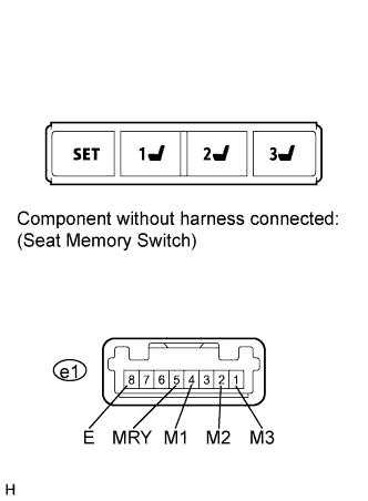
Remove the seat memory switch (Click here).
-
Measure the resistance according to the value(s) in the table below.
Standard Resistance Tester Connection Switch Condition Specified Condition e1-4 (M1) - e1-8 (E) M1 switch pressed Below 1 Ω e1-2 (M2) - e1-8 (E) M2 switch pressed Below 1 Ω e1-1 (M3) - e1-8 (E) M3 switch pressed Below 1 Ω e1-5 (MRY) - e1-8 (E) SET switch pressed Below 1 Ω
- OKClick here
- NGClick here
-
- Click here
CHECK HARNESS AND CONNECTOR (OUTER MIRROR CONTROL ECU ASSEMBLY - SEAT MEMORY SWITCH)
-
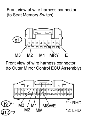
Disconnect the I9*1, J12*2 connector from the outer mirror control ECU assembly.
-
Measure the resistance according to the value(s) in the table below.
Standard Resistance Table 4. for RHD Tester Connection Condition Specified Condition e1-1 (M3) - I9-6 (M3) Always Below 1 Ω e1-2 (M2) - I9-7 (M2) Always Below 1 Ω e1-4 (M1) - I9-8 (M1) Always Below 1 Ω e1-5 (MRY) - I9-9 (MM) Always Below 1 Ω e1-8 (E) - I9-10 (MSWE) Always Below 1 Ω e1-1 (M3) - Body ground Always 10 kΩ or higher e1-2 (M2) - Body ground Always 10 kΩ or higher e1-4 (M1) - Body ground Always 10 kΩ or higher e1-5 (MRY) - Body ground Always 10 kΩ or higher e1-8 (E) - Body ground Always 10 kΩ or higher Table 5. for LHD Tester Connection Condition Specified Condition e1-1 (M3) - J12-6 (M3) Always Below 1 Ω e1-2 (M2) - J12-7 (M2) Always Below 1 Ω e1-4 (M1) - J12-8 (M1) Always Below 1 Ω e1-5 (MRY) - J12-9 (MM) Always Below 1 Ω e1-8 (E) - J12-10 (MSWE) Always Below 1 Ω e1-1 (M3) - Body ground Always 10 kΩ or higher e1-2 (M2) - Body ground Always 10 kΩ or higher e1-4 (M1) - Body ground Always 10 kΩ or higher e1-5 (MRY) - Body ground Always 10 kΩ or higher e1-8 (E) - Body ground Always 10 kΩ or higher
- OKClick here
- NGClick here
-
- Click here
GO TO CAN COMMUNICATION SYSTEMClick here
- Click here
GO TO OTHER FLOW CHART (Power Seat does not Operate with Front Power Seat Switch)Click here
- Click here
REPLACE POSITION CONTROL ECU AND SWITCH ASSEMBLYClick here
- Click here
REPLACE POSITION CONTROL ECU AND SWITCH ASSEMBLYClick here
- Click here
END (OUTER MIRROR CONTROL ECU ASSEMBLY IS DEFECTIVE)
- Click here
GO TO SFI SYSTEM (P0705)Click here
- Click here
REPLACE ECMClick here
- Click here
REPLACE POSITION CONTROL ECU AND SWITCH ASSEMBLYClick here
- Click here
REPLACE SEAT MEMORY SWITCHClick here
- Click here
REPAIR OR REPLACE HARNESS OR CONNECTOR (OUTER MIRROR CONTROL ECU ASSEMBLY - SEAT MEMORY SWITCH)
- Click here
REPLACE OUTER MIRROR CONTROL ECU ASSEMBLYClick here
- Click here
GO TO CVT SYSTEM (P0705)Click here
- Click here
REPLACE ECMClick here