FRONT POWER SEAT CONTROL SYSTEM (for Driver Side) One or more Power Seat Motors do not Operate
DESCRIPTION
When a switch of position control ECU and switch assembly is operated, a command signal is sent to the ECU of the position control ECU and switch assembly. The position control ECU and switch assembly then controls the appropriate seat motor as needed. The position control ECU and switch assembly is designed so that a malfunction of the seat memory system will not interfere with manual seat control.
Tech Tips
The position control ECU and seat adjustment switches are built into an assembly that is referred to as the position control ECU and switch assembly.
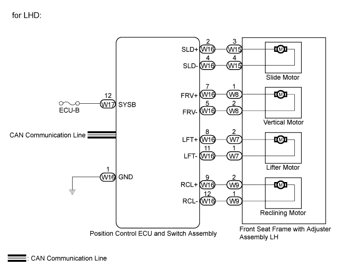
WIRING DIAGRAM

INSPECTION PROCEDURE
PROCEDURE
-
READ VALUE USING INTELLIGENT TESTER (POSITION CONTROL ECU AND SWITCH ASSEMBLY)
-
Connect the intelligent tester to the DLC3.
-
Turn the engine switch on (IG).
-
Turn the intelligent tester on.
-
Enter the following menus: Body / D-Seat / Data List.
-
Read the Data List according to the display on the intelligent tester.
D-Seat Tester Display Measurement Item/Range Normal Condition Diagnostic Note Reclining Rear Reclining switch signal (Rearward) / ON or OFF ON: Reclining switch (Rearward) on
OFF: Reclining switch (Rearward) off
- Reclining Front Reclining switch signal (Forward) / ON or OFF ON: Reclining switch (Forward) on
OFF: Reclining switch (Forward) off
- Front Vertical Down Front vertical switch signal (Downward) / ON or OFF ON: Front vertical switch (Downward) on
OFF: Front vertical switch (Downward) off
- Front Vertical Up Front vertical switch signal (Upward) / ON or OFF ON: Front vertical switch (Upward) on
OFF: Front vertical switch (Upward) off
- Lifter Switch Down Lifter switch signal (Downward) / ON or OFF ON: Lifter switch (Downward) on
OFF: Lifter switch (Downward) off
- Lifter Switch Up Lifter switch signal (Upward) / ON or OFF ON: Lifter switch (Upward) on
OFF: Lifter switch (Upward) off
- Slide Rear Sliding switch signal (Rearward) / ON or OFF ON: Sliding switch (Rearward) on
OFF: Sliding switch (Rearward) off
- Slide Front Sliding switch signal (Forward) / ON or OFF ON: Sliding switch (Forward) on
OFF: Sliding switch (Forward) off
- OK ON or OFF is displayed on the intelligent tester according to the table above.
NG 
CHECK HARNESS AND CONNECTOR (POSITION CONTROL ECU AND SWITCH ASSEMBLY) Click here
OK 
-
-
PERFORM ACTIVE TEST USING INTELLIGENT TESTER
-
Enter the following menus: Body / D-Seat / Active Test.
-
Perform the Active Test according to the display on the intelligent tester.
D-Seat Tester Display Test Part Control Range Diagnostic Note Seat Reclining Seat reclining operation Front / OFF / Rear - Front Vertical Operation Seat front vertical operation Up / OFF / Down - Lifter Operation Seat lifter operation Up / OFF / Down - Seat Slide Operation Seat sliding operation Front / OFF / Rear - Result Result Proceed to OK A NG (for RHD) B NG (for LHD) C OK The power seat motors operate normally.
B
INSPECT FRONT SEAT FRAME WITH ADJUSTER ASSEMBLY RH Click here
C
INSPECT FRONT SEAT FRAME WITH ADJUSTER ASSEMBLY LH Click here
A 
REPLACE POSITION CONTROL ECU AND SWITCH ASSEMBLY Click here
-
-
INSPECT FRONT SEAT FRAME WITH ADJUSTER ASSEMBLY RH
-
Remove the front seat frame with adjuster assembly RH Click here.
-
Disconnect the V14, V2, V3 and V4 connectors from each motor.
-
Check operation of the slide motor.
-
Check if the seat moves smoothly when the battery is connected to the slide motor connector terminals.
OK Measurement Condition Specified Condition Battery positive (+) → 3
Battery negative (-) → 4
Forward Battery positive (+) → 4
Battery negative (-) → 3
Rearward
-
-
Check operation of the front vertical motor.
-
Check if the seat moves smoothly when the battery is connected to the front vertical motor connector terminals.
OK Measurement Condition Specified Condition Battery positive (+) → 2
Battery negative (-) → 1
Upward Battery positive (+) → 1
Battery negative (-) → 2
Downward
-
-

Check operation of the lifter motor.
-
Check if the seat moves smoothly when the battery is connected to the lifter motor connector terminals.
OK Measurement Condition Specified Condition Battery positive (+) → 1
Battery negative (-) → 2
Forward Battery positive (+) → 2
Battery negative (-) → 1
Rearward
-
-
Check operation of the reclining motor.
-
Check if the seat moves smoothly when the battery is connected to the reclining motor connector terminals.
OK Measurement Condition Specified Condition Battery positive (+) → 2
Battery negative (-) → 1
Forward Battery positive (+) → 1
Battery negative (-) → 2
Rearward
-
NG 
REPLACE FRONT SEAT FRAME WITH ADJUSTER ASSEMBLY RH Click here
OK
-
-
CHECK HARNESS AND CONNECTOR (POSITION CONTROL ECU AND SWITCH ASSEMBLY - POWER SEAT MOTOR)
-
Disconnect the V15 connector from the position control ECU and switch assembly.
-
Measure the resistance according to the value(s) in the table below.
Standard Resistance Tester Connection Condition Specified Condition V15-2 (SLD+) - V14-3 Always Below 1 Ω V15-4 (SLD-) - V14-4 Always Below 1 Ω V15-5 (FRV-) - V3-1 Always Below 1 Ω V15-7 (FRV+) - V3-2 Always Below 1 Ω V15-8 (LFT+) - V2-1 Always Below 1 Ω V15-9 (RCL+) - V4-2 Always Below 1 Ω V15-11 (LFT-) - V2-2 Always Below 1 Ω V15-12 (RCL-) - V4-1 Always Below 1 Ω V15-2 (SLD+) - Body ground Always 10 kΩ or higher V15-4 (SLD-) - Body ground Always 10 kΩ or higher V15-5 (FRV-) - Body ground Always 10 kΩ or higher V15-7 (FRV+) - Body ground Always 10 kΩ or higher V15-8 (LFT+) - Body ground Always 10 kΩ or higher V15-9 (RCL+) - Body ground Always 10 kΩ or higher V15-11 (LFT-) - Body ground Always 10 kΩ or higher V15-12 (RCL-) - Body ground Always 10 kΩ or higher
NG
REPAIR OR REPLACE HARNESS OR CONNECTOR (POSITION CONTROL ECU AND SWITCH ASSEMBLY - POWER SEAT MOTOR)
OK
REPLACE POSITION CONTROL ECU AND SWITCH ASSEMBLY Click here
-
-
INSPECT FRONT SEAT FRAME WITH ADJUSTER ASSEMBLY LH
-
Remove the front seat frame with adjuster assembly LH Click here.
-
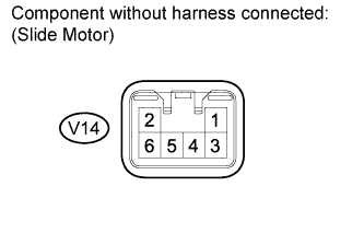
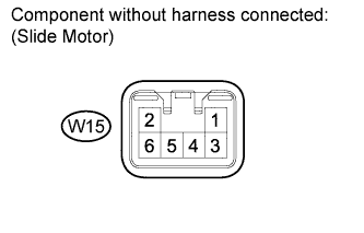
Disconnect the W15, W7, W8 and W9 connectors from each motor.
-
Check operation of the slide motor.
-
Check if the seat moves smoothly when the battery is connected to the slide motor connector terminals.
OK Measurement Condition Specified Condition Battery positive (+) → 3
Battery negative (-) → 4
Forward Battery positive (+) → 4
Battery negative (-) → 3
Rearward
-
-
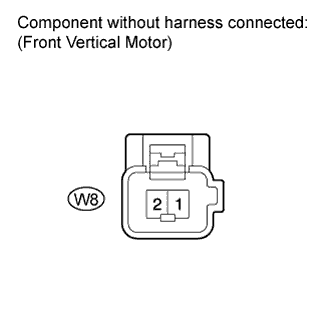
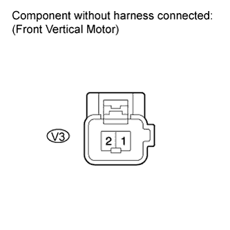
Check operation of the front vertical motor.
-
Check if the seat moves smoothly when the battery is connected to the front vertical motor connector terminals.
OK Measurement Condition Specified Condition Battery positive (+) → 1
Battery negative (-) → 2
Upward Battery positive (+) → 2
Battery negative (-) → 1
Downward
-
-
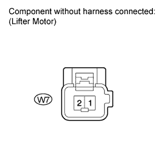
Check operation of the lifter motor.
-
Check if the seat moves smoothly when the battery is connected to the lifter motor connector terminals.
OK Measurement Condition Specified Condition Battery positive (+) → 1
Battery negative (-) → 2
Forward Battery positive (+) → 2
Battery negative (-) → 1
Rearward
-
-
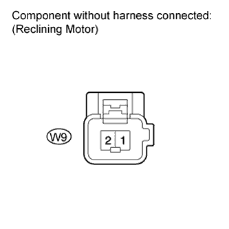
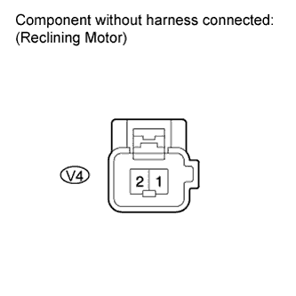
Check operation of the reclining motor.
-
Check if the seat moves smoothly when the battery is connected to the reclining motor connector terminals.
OK Measurement Condition Specified Condition Battery positive (+) → 2
Battery negative (-) → 1
Forward Battery positive (+) → 1
Battery negative (-) → 2
Rearward
-
NG
REPLACE FRONT SEAT FRAME WITH ADJUSTER ASSEMBLY LH Click here
OK
-
-
CHECK HARNESS AND CONNECTOR (POSITION CONTROL ECU AND SWITCH ASSEMBLY - POWER SEAT MOTOR)
-
Disconnect the W16 connector from the position control ECU and switch assembly.
-
Measure the resistance according to the value(s) in the table below.
Standard Resistance Tester Connection Condition Specified Condition W16-2 (SLD+) - W15-3 Always Below 1 Ω W16-4 (SLD-) - W15-4 Always Below 1 Ω W16-5 (FRV-) - W8-2 Always Below 1 Ω W16-7 (FRV+) - W8-1 Always Below 1 Ω W16-8 (LFT+) - W7-2 Always Below 1 Ω W16-9 (RCL+) - W9-2 Always Below 1 Ω W16-11 (LFT-) - W7-1 Always Below 1 Ω W16-12 (RCL-) - W9-1 Always Below 1 Ω W16-2 (SLD+) - Body ground Always 10 kΩ or higher W16-4 (SLD-) - Body ground Always 10 kΩ or higher W16-5 (FRV-) - Body ground Always 10 kΩ or higher W16-7 (FRV+) - Body ground Always 10 kΩ or higher W16-8 (LFT+) - Body ground Always 10 kΩ or higher W16-9 (RCL+) - Body ground Always 10 kΩ or higher W16-11 (LFT-) - Body ground Always 10 kΩ or higher W16-12 (RCL-) - Body ground Always 10 kΩ or higher
NG
REPAIR OR REPLACE HARNESS OR CONNECTOR (POSITION CONTROL ECU AND SWITCH ASSEMBLY - POWER SEAT MOTOR)
OK
REPLACE POSITION CONTROL ECU AND SWITCH ASSEMBLY Click here
-
-
CHECK HARNESS AND CONNECTOR (POSITION CONTROL ECU AND SWITCH ASSEMBLY)
-
Disconnect the V16*1, W17*2 connector from the position control ECU and switch assembly.
-
*1: for RHD
-
*2: for LHD
-
-
Measure the voltage according to the value(s) in the table below.
Standard Voltage for RHD Tester Connection Condition Specified Condition V16-12 (SYSB) - Body ground Always 11 to 14 V for LHD Tester Connection Condition Specified Condition W17-12 (SYSB) - Body ground Always 11 to 14 V
NG
REPAIR OR REPLACE HARNESS OR CONNECTOR (POSITION CONTROL ECU AND SWITCH ASSEMBLY)
OK
REPLACE POSITION CONTROL ECU AND SWITCH ASSEMBLY Click here
-