FRONT POWER SEAT CONTROL SYSTEM (for Driver Side), Diagnostic DTC:B2658

| DTC Code | DTC Name |
|---|---|
| B2658 | Short in Sensor with Motor Power Supply Circuit |
DESCRIPTION
This DTC is stored if sensor voltage does not reach the designated voltage while the slide motor is operating.
| DTC Code | DTC Detection Condition | Trouble Area |
|---|---|---|
| B2658 | Malfunction in supply voltage for the seat slide control position sensor |
|
WIRING DIAGRAM

INSPECTION PROCEDURE
PROCEDURE
-
CHECK FOR DTC
-
Connect the intelligent tester to the DLC3.
-
Turn the engine switch on (IG).
-
Turn the intelligent tester on.
-
Enter the following menus: Body / D-Seat / Trouble Codes.
-
Clear the DTCs Click here.
-
Check for DTCs Click here.
Result Result Proceed to DTC B2658 is output A DTC B2658 is not output B
B 
USE SIMULATION METHOD TO CHECK Click here
A 
-
-
CHECK HARNESS AND CONNECTOR (POSITION CONTROL ECU AND SWITCH ASSEMBLY - SLIDE MOTOR)
-
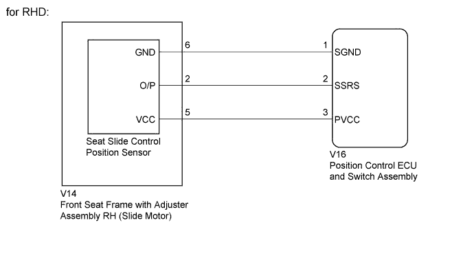
Disconnect the V16*1 or W17*2 connector from the position control ECU and switch assembly.
-
*1: for RHD
-
*2: for LHD
-
-
Disconnect the V14*1, W15*2 connector from the slide motor.
-
Measure the resistance according to the value(s) in the table below.
-
*1: for RHD
-
*2: for LHD
Standard Resistance for RHD Tester Connection Condition Specified Condition V16-3 (PVCC) - V14-5 (VCC) Always Below 1 Ω V16-2 (SSRS) - V14-2 (O/P) Always Below 1 Ω V16-1 (SGND) - V14-6 (GND) Always Below 1 Ω V16-3 (PVCC) - Body ground Always 10 kΩ or higher V16-2 (SSRS) - Body ground Always 10 kΩ or higher V16-1 (SGND) - Body ground Always 10 kΩ or higher for LHD Tester Connection Condition Specified Condition W17-3 (PVCC) - W15-5 (VCC) Always Below 1 Ω W17-2 (SSRS) - W15-2 (O/P) Always Below 1 Ω W17-1 (SGND) - W15-6 (GND) Always Below 1 Ω W17-3 (PVCC) - Body ground Always 10 kΩ or higher W17-2 (SSRS) - Body ground Always 10 kΩ or higher W17-1 (SGND) - Body ground Always 10 kΩ or higher -
NG
REPAIR OR REPLACE HARNESS OR CONNECTOR
OK
-
-
CHECK FRONT SEAT FRAME WITH ADJUSTER ASSEMBLY (SEAT SLIDE POSITION SENSOR)
-
Reconnect the V16*1 or W17*2 connector to the position control ECU and switch assembly.
-
*1: for RHD
-
*2: for LHD
-
-
Measure the voltage according to the value(s) in the table below.
Standard Voltage for RHD Tester Connection Switch Condition Specified Condition V14-5 (VCC) - V14-6 (GND) Slide switch on 5.5 to 6.5 V for LHD Tester Connection Switch Condition Specified Condition W15-5 (VCC) - W15-6 (GND) Slide switch on 5.5 to 6.5 V
NG
REPLACE POSITION CONTROL ECU AND SWITCH ASSEMBLY Click here
OK 
REPLACE FRONT SEAT FRAME WITH ADJUSTER ASSEMBLY Click here
-