| DTC Code | DTC Name |
|---|---|
| B1622/81 | Lost Communication with Driver Side - Side Airbag Sensor Assembly |
| B1623/81 | Driver Side - Side Airbag Sensor Assembly Initialization Incomplete |
| B1632/81 | Lost Communication with Driver Side Rear Airbag Sensor |
| B1633/81 | Driver Side Rear Airbag Sensor Initialization Incomplete |
| B1642/81 | Lost Communication with Driver Side Satellite Sensor Bus |
| B1643/81 | Driver Side Satellite Sensor Bus Initialization Incomplete |
| B1666/81 | Lost Communication with Driver Side Center Floor Airbag Sensor |
| B1667/81 | Driver Side Center Floor Airbag Sensor Initialization Incomplete |
| B1673/81 | Lost Communication with Driver Side Door Side Airbag Sensor |
| B1674/81 | Driver Side Door Side Airbag Sensor Initialization Incomplete |
| B1676/81 | Lost Communication with Driver Side Rear Floor Airbag Sensor |
| B1677/81 | Driver Side Rear Floor Airbag Sensor Initialization Incomplete |
DESCRIPTION
-
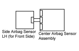
for LHD:
The driver side - side collision sensor circuit (to determine deployment of the front seat side airbag assembly LH and curtain shield airbag assembly LH) is composed of the center airbag sensor assembly, side airbag sensor LH (for front side), rear airbag sensor LH, side airbag sensor LH (for rear side) and rear floor airbag sensor.
The side airbag sensor LH (for front side), rear airbag sensor LH, side airbag sensor LH (for rear side) and rear floor airbag sensor detect impacts to the vehicle and send signals to the center airbag sensor assembly to determine if the airbag should be deployed.
These DTCs are recorded when a malfunction is detected for the driver side - side collision sensor circuit (to determine deployment of the front seat side airbag assembly LH and curtain shield airbag assembly LH).
DTC No. DTC Detection Condition Trouble Area B1622/81
B1623/81
B1632/81
B1633/81
B1642/81
B1643/81
B1666/81
B1667/81
B1673/81
B1674/81
B1676/81
B1677/81
-
The center airbag sensor assembly receives a line short circuit signal, an open circuit signal, a short circuit to ground signal or a short circuit to B+ signal in the driver side - side collision sensor circuit (to determine deployment of the front seat side airbag assembly LH and curtain shield airbag assembly LH).
-
Side airbag sensor LH (for front side) malfunction
-
Rear airbag sensor LH malfunction
-
Side airbag sensor LH (for rear side) malfunction
-
Rear floor airbag sensor malfunction
-
Center airbag sensor assembly malfunction
-
No. 2 floor wire
-
No. 2 rear door wire
-
Side airbag sensor LH (for front side)
-
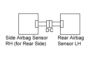
Rear airbag sensor LH
-
Side airbag sensor LH (for rear side)
-
Rear floor airbag sensor
-
Center airbag sensor assembly
-
-
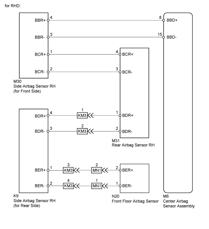
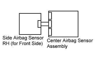
for RHD:
The driver side - side collision sensor circuit (to determine deployment of the front seat side airbag assembly RH and curtain shield airbag assembly RH) is composed of the center airbag sensor assembly, side airbag sensor RH (for front side), rear airbag sensor RH, side airbag sensor RH (for rear side) and front floor airbag sensor.
The side airbag sensor RH (for front side), rear airbag sensor RH, side airbag sensor RH (for rear side) and front floor airbag sensor detect impacts to the vehicle and send signals to the center airbag sensor assembly to determine if the airbag should be deployed.
These DTCs are recorded when a malfunction is detected for the driver side - side collision sensor circuit (to determine deployment of the front seat side airbag assembly RH and curtain shield airbag assembly RH).
DTC No. DTC Detection Condition Trouble Area B1622/81
B1623/81
B1632/81
B1633/81
B1642/81
B1643/81
B1666/81
B1667/81
B1673/81
B1674/81
B1676/81
B1677/81
-
The center airbag sensor assembly receives a line short circuit signal, an open circuit signal, a short circuit to ground signal or a short circuit to B+ signal in the driver side - side collision sensor circuit (to determine deployment of the front seat side airbag assembly RH and curtain shield airbag assembly RH).
-
Side airbag sensor RH (for front side) malfunction
-
Rear airbag sensor RH malfunction
-
Side airbag sensor RH (for rear side) malfunction
-
Front floor airbag sensor malfunction
-
Center airbag sensor assembly malfunction
-
Floor wire
-
No. 2 floor wire
-
No. 1 rear door wire
-
Side airbag sensor RH (for front side)
-
Rear airbag sensor RH
-
Side airbag sensor RH (for rear side)
-
Front floor airbag sensor
-
Center airbag sensor assembly
-
INSPECTION PROCEDURE
PROCEDURE
- Click here
CHECK PRESENT DTC
-
Turn the engine switch on (IG), and wait for at least 60 seconds.
-
Check for present DTCs (Click here).
Result Result Proceed to Present DTC B1643 is output. A Present DTC B1642 or 81 is output. B Present DTC B1623, B1633 or B1674 is output. C Present DTC B1666, B1667, B1676 or B1677 is output. D Present DTC B1622, B1632, or B1673 is output. E Tip:
-
DTCs indicating communication errors will be changed to DTCs indicating errors in initialization by turning the engine switch off and then on (IG) again.
-
Codes other than present DTCs B1622, B1623, B1632, B1633, B1642, B1643, B1666, B1667, B1673, B1674, B1676, B1677 and 81 may be output at this time, but they are not related to this check.
-
-
- Click here
CHECK PAST DTC
-
Turn the engine switch on (IG), and wait for at least 60 seconds.
-
Check for past DTCs (Click here).
Result Result Proceed to Past DTCs B1622, B1666 and B1676 are not output. A Past DTC B1622 is output. B Past DTC B1666 or B1676 is output. C Tip:Codes other than past DTCs B1622, B1666 and B1676 may be output at this time, but they are not related to this check.
-
- Click here
CHECK CONNECTORS
-
for LHD:
-
Turn the engine switch off.
-
Disconnect the cable from the negative (-) battery terminal, and wait for at least 90 seconds.
-
Check that the connectors are properly connected to the center airbag sensor assembly, side airbag sensor LH (for front side), rear airbag sensor LH, side airbag sensor LH (for rear side) and rear floor airbag sensor. Also check that the connectors that link the No. 2 floor wire and No. 2 rear door wire are properly connected.
OK The connectors are properly connected. Tip:If the connectors are not connected securely, reconnect the connectors and proceed to the next inspection.
-
Disconnect the connectors from the center airbag sensor assembly, side airbag sensor LH (for front side), rear airbag sensor LH, side airbag sensor LH (for rear side) and rear floor airbag sensor. Also disconnect the connectors that link the No. 2 floor wire and No. 2 rear door wire.
-
Check that the terminals of the connectors are not damaged.
OK The terminals are not deformed or damaged.
-
-
for RHD:
-
Turn the engine switch off.
-
Disconnect the cable from the negative (-) battery terminal, and wait for at least 90 seconds.
-
Check that the connectors are properly connected to the center airbag sensor assembly, side airbag sensor RH (for front side), rear airbag sensor RH, side airbag sensor RH (for rear side) and front floor airbag sensor. Also check that the connectors that link the floor wire, No. 2 floor wire and No. 1 rear door wire are properly connected.
OK The connectors are properly connected. Tip:If the connectors are not connected securely, reconnect the connectors and proceed to the next inspection.
-
Disconnect the connectors from the center airbag sensor assembly, side airbag sensor RH (for front side), rear airbag sensor RH, side airbag sensor RH (for rear side) and front floor airbag sensor. Also disconnect the connectors that link the floor wire, No. 2 floor wire and No. 1 rear door wire.
-
Check that the terminals of the connectors are not damaged.
OK The terminals are not deformed or damaged.
-
- OKClick here
- NGClick here
-
- Click here
CHECK WIRE HARNESS (OPEN)
-
for LHD:
-
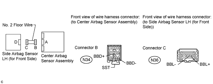
Using SST, connect terminals 8 (BBD+) and 15 (BBD-) of connector B.
Note:Do not forcibly insert SST into the terminals of the connector when connecting.
-
Measure the resistance according to the value(s) in the table below.
Standard Resistance Tester Connection Condition Specified Condition N36-4 (BBL+) - N36-3 (BBL-) Always Below 1 Ω Table 1. Result Result Proceed to OK A NG B
09843-18040 -
-
for RHD:
-
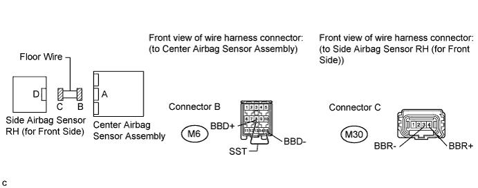
Using SST, connect terminals 8 (BBD+) and 15 (BBD-) of connector B.
Note:Do not forcibly insert SST into the terminals of the connector when connecting.
-
Measure the resistance according to the value(s) in the table below.
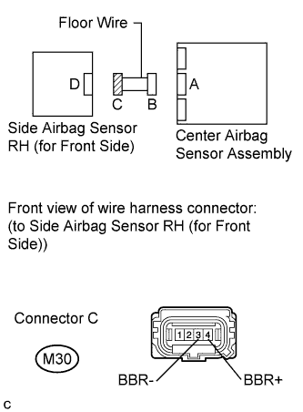
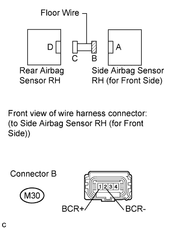
Standard Resistance Tester Connection Condition Specified Condition M30-4 (BBR+) - M30-3 (BBR-) Always Below 1 Ω Table 2. Result Result Proceed to OK A NG C
09843-18040 -
-
- Click here
CHECK WIRE HARNESS (SHORT)
-
for LHD:
-
Disconnect SST from connector B.
-
Measure the resistance according to the value(s) in the table below.
Standard Resistance Tester Connection Condition Specified Condition N36-4 (BBL+) - N36-3 (BBL-) Always 1 MΩ or higher Table 3. Result Result Proceed to OK A NG B
-
-
for RHD:
-
Disconnect SST from connector B.
-
Measure the resistance according to the value(s) in the table below.
Standard Resistance Tester Connection Condition Specified Condition M30-4 (BBR+) - M30-3 (BBR-) Always 1 MΩ or higher Table 4. Result Result Proceed to OK A NG C
-
-
- Click here
CHECK WIRE HARNESS (SHORT TO B+)
-
for LHD:
-
Connect the cable to the negative (-) battery terminal.
-
Turn the engine switch on (IG).
-
Measure the voltage according to the value(s) in the table below.
Standard Voltage Tester Connection Switch Condition Specified Condition N36-4 (BBL+) - Body ground Engine switch on (IG) Below 1 V N36-3 (BBL-) - Body ground Engine switch on (IG) Below 1 V Table 5. Result Result Proceed to OK A NG B
-
-
for RHD:
-
Connect the cable to the negative (-) battery terminal.
-
Turn the engine switch on (IG).
-
Measure the voltage according to the value(s) in the table below.
Standard Voltage Tester Connection Switch Condition Specified Condition M30-4 (BBR+) - Body ground Engine switch on (IG) Below 1 V M30-3 (BBR-) - Body ground Engine switch on (IG) Below 1 V Table 6. Result Result Proceed to OK A NG C
-
-
- Click here
CHECK WIRE HARNESS (SHORT TO GROUND)
-
for LHD:
-
Turn the engine switch off.
-
Disconnect the cable from the negative (-) battery terminal, and wait for at least 90 seconds.
-
Measure the resistance according to the value(s) in the table below.
Standard Resistance Tester Connection Condition Specified Condition N36-4 (BBL+) - Body ground Always 1 MΩ or higher N36-3 (BBL-) - Body ground Always 1 MΩ or higher Table 7. Result Result Proceed to OK A NG B
-
-
for RHD:
-
Turn the engine switch off.
-
Disconnect the cable from the negative (-) battery terminal, and wait for at least 90 seconds.
-
Measure the resistance according to the value(s) in the table below.
Standard Resistance Tester Connection Condition Specified Condition M30-4 (BBR+) - Body ground Always 1 MΩ or higher M30-3 (BBR-) - Body ground Always 1 MΩ or higher Table 8. Result Result Proceed to OK A NG C
-
-
- Click here
CHECK WIRE HARNESS (OPEN)
-
for LHD:
-
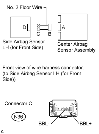
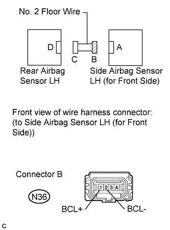
Using SST, connect terminals 4 (BCL+) and 3 (BCL-) of connector C.
Note:Do not forcibly insert SST into the terminals of the connector when connecting.
-
Measure the resistance according to the value(s) in the table below.
Standard Resistance Tester Connection Condition Specified Condition N36-1 (BCL+) - N36-2 (BCL-) Always Below 1 Ω Table 9. Result Result Proceed to OK A NG B
09843-18040 -
-
for RHD:
-
Using SST, connect terminals 4 (BCR+) and 3 (BCR-) of connector C.
Note:Do not forcibly insert SST into the terminals of the connector when connecting.
-
Measure the resistance according to the value(s) in the table below.
Standard Resistance Tester Connection Condition Specified Condition M30-1 (BCR+) - M30-2 (BCR-) Always Below 1 Ω Table 10. Result Result Proceed to OK A NG C
09843-18040 -
-
- Click here
CHECK WIRE HARNESS (SHORT)
-
for LHD:
-
Disconnect SST from connector C.
-
Measure the resistance according to the value(s) in the table below.
Standard Resistance Tester Connection Condition Specified Condition N36-1 (BCL+) - N36-2 (BCL-) Always 1 MΩ or higher Table 11. Result Result Proceed to OK A NG B
-
-
for RHD:
-
Disconnect SST from connector C.
-
Measure the resistance according to the value(s) in the table below.
Standard Resistance Tester Connection Condition Specified Condition M30-1 (BCR+) - M30-2 (BCR-) Always 1 MΩ or higher Table 12. Result Result Proceed to OK A NG C
-
-
- Click here
CHECK WIRE HARNESS (SHORT TO B+)
-
for LHD:
-
Connect the cable to the negative (-) battery terminal.
-
Turn the engine switch on (IG).
-
Measure the voltage according to the value(s) in the table below.
Standard Voltage Tester Connection Switch Condition Specified Condition N36-1 (BCL+) - Body ground Engine switch on (IG) Below 1 V N36-2 (BCL-) - Body ground Engine switch on (IG) Below 1 V Table 13. Result Result Proceed to OK A NG B
-
-
for RHD:
-
Connect the cable to the negative (-) battery terminal.
-
Turn the engine switch on (IG).
-
Measure the voltage according to the value(s) in the table below.
Standard Voltage Tester Connection Switch Condition Specified Condition M30-1 (BCR+) - Body ground Engine switch on (IG) Below 1 V M30-2 (BCR-) - Body ground Engine switch on (IG) Below 1 V Table 14. Result Result Proceed to OK A NG C
-
-
- Click here
CHECK WIRE HARNESS (SHORT TO GROUND)
-
for LHD:
-
Turn the engine switch off.
-
Disconnect the cable from the negative (-) battery terminal, and wait for at least 90 seconds.
-
Measure the resistance according to the value(s) in the table below.
Standard Resistance Tester Connection Condition Specified Condition N36-1 (BCL+) - Body ground Always 1 MΩ or higher N36-2 (BCL-) - Body ground Always 1 MΩ or higher Table 15. Result Result Proceed to OK A NG B
-
-
for RHD:
-
Turn the engine switch off.
-
Disconnect the cable from the negative (-) battery terminal, and wait for at least 90 seconds.
-
Measure the resistance according to the value(s) in the table below.
Standard Resistance Tester Connection Condition Specified Condition M30-1 (BCR+) - Body ground Always 1 MΩ or higher M30-2 (BCR-) - Body ground Always 1 MΩ or higher Table 16. Result Result Proceed to OK A NG C
-
-
- Click here
CHECK WIRE HARNESS (OPEN)
-
for LHD:
-
Connect the connectors that link the No. 2 floor wire and No. 2 rear door wire.
-
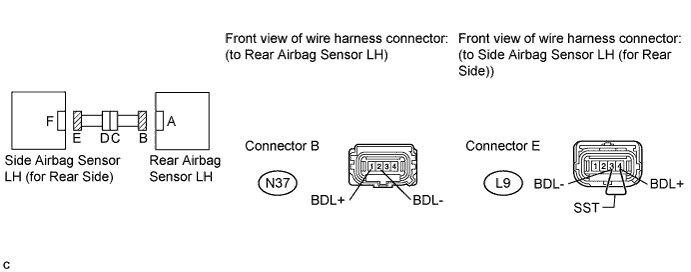
Using SST, connect terminals 4 (BDL+) and 3 (BDL-) of connector E.
Note:Do not forcibly insert SST into the terminals of the connector when connecting.
-
Measure the resistance according to the value(s) in the table below.
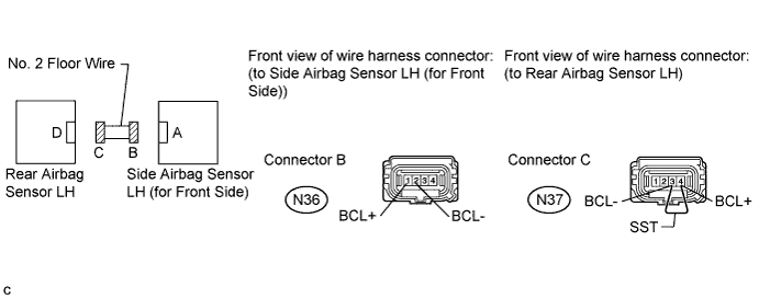
Standard Resistance Tester Connection Condition Specified Condition N37-1 (BDL+) - N37-2 (BDL-) Always Below 1 Ω
09843-18040 -
-
for RHD:
-
Connect the connectors that link the floor wire and No. 1 rear door wire.
-
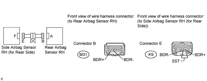
Using SST, connect terminals 4 (BDR+) and 3 (BDR-) of connector E.
Note:Do not forcibly insert SST into the terminals of the connector when connecting.
-
Measure the resistance according to the value(s) in the table below.
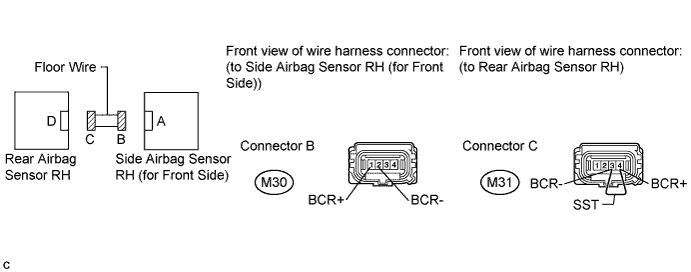
Standard Resistance Tester Connection Condition Specified Condition M31-1 (BDR+) - M31-2 (BDR-) Always Below 1 Ω
09843-18040 -
- OKClick here
- NGClick here
-
- Click here
CHECK WIRE HARNESS (SHORT)
-
for LHD:
-
Disconnect SST from connector E.
-
Measure the resistance according to the value(s) in the table below.
Standard Resistance Tester Connection Condition Specified Condition N37-1 (BDL+) - N37-2 (BDL-) Always 1 MΩ or higher
-
-
for RHD:
-

Disconnect SST from connector E.
-
Measure the resistance according to the value(s) in the table below.
Standard Resistance Tester Connection Condition Specified Condition M31-1 (BDR+) - M31-2 (BDR-) Always 1 MΩ or higher
-
- OKClick here
- NGClick here
-
- Click here
CHECK WIRE HARNESS (SHORT TO B+)
-
for LHD:
-
Connect the cable to the negative (-) battery terminal.
-
Turn the engine switch on (IG).
-
Measure the voltage according to the value(s) in the table below.
Standard Voltage Tester Connection Switch Condition Specified Condition N37-1 (BDL+) - Body ground Engine switch on (IG) Below 1 V N37-2 (BDL-) - Body ground Engine switch on (IG) Below 1 V
-
-
for RHD:
-
Connect the cable to the negative (-) battery terminal.
-
Turn the engine switch on (IG).
-
Measure the voltage according to the value(s) in the table below.
Standard Voltage Tester Connection Switch Condition Specified Condition M31-1 (BDR+) - Body ground Engine switch on (IG) Below 1 V M31-2 (BDR-) - Body ground Engine switch on (IG) Below 1 V
-
- OKClick here
- NGClick here
-
- Click here
CHECK WIRE HARNESS (SHORT TO GROUND)
-
for LHD:
-
Turn the engine switch off.
-
Disconnect the cable from the negative (-) battery terminal, and wait for at least 90 seconds.
-
Measure the resistance according to the value(s) in the table below.
Standard Resistance Tester Connection Condition Specified Condition N37-1 (BDL+) - Body ground Always 1 MΩ or higher N37-2 (BDL-) - Body ground Always 1 MΩ or higher
-
-
for RHD:
-
Turn the engine switch off.
-
Disconnect the cable from the negative (-) battery terminal, and wait for at least 90 seconds.
-
Measure the resistance according to the value(s) in the table below.
Standard Resistance Tester Connection Condition Specified Condition M31-1 (BDR+) - Body ground Always 1 MΩ or higher M31-2 (BDR-) - Body ground Always 1 MΩ or higher
-
- OKClick here
- NGClick here
-
- Click here
CHECK WIRE HARNESS (OPEN)
-
for LHD:
-
Connect the connectors that link the No. 2 floor wire and No. 2 rear door wire.
-
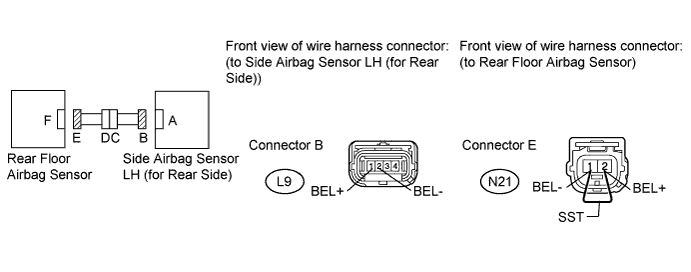
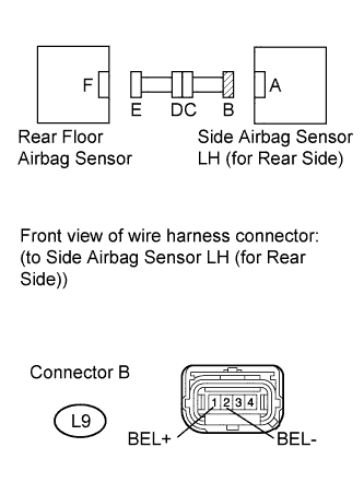
Using SST, connect terminals 2 (BEL+) and 1 (BEL-) of connector E.
Note:Do not forcibly insert SST into the terminals of the connector when connecting.
-
Measure the resistance according to the value(s) in the table below.
Standard Resistance Tester Connection Condition Specified Condition L9-1 (BEL+) - L9-2 (BEL-) Always Below 1 Ω Table 17. Result Result Proceed to OK A NG B
09843-18040 -
-
for RHD:
-
Connect the connectors that link the floor wire, No. 2 floor wire and No. 1 rear door wire.
-
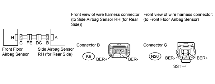
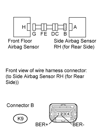
Using SST, connect terminals 2 (BER+) and 1 (BER-) of connector G.
Note:Do not forcibly insert SST into the terminals of the connector when connecting.
-
Measure the resistance according to the value(s) in the table below.
Standard Resistance Tester Connection Condition Specified Condition K9-1 (BER+) - K9-2 (BER-) Always Below 1 Ω Table 18. Result Result Proceed to OK A NG C
09843-18040 -
-
- Click here
CHECK WIRE HARNESS (SHORT)
-
for LHD:
-
Disconnect SST from connector E.
-
Measure the resistance according to the value(s) in the table below.
Standard Resistance Tester Connection Condition Specified Condition L9-1 (BEL+) - L9-2 (BEL-) Always 1 MΩ or higher Table 19. Result Result Proceed to OK A NG B
-
-
for RHD:
-
Disconnect SST from connector G.
-
Measure the resistance according to the value(s) in the table below.
Standard Resistance Tester Connection Condition Specified Condition K9-1 (BER+) - K9-2 (BER-) Always 1 MΩ or higher Table 20. Result Result Proceed to OK A NG C
-
-
- Click here
CHECK WIRE HARNESS (SHORT TO B+)
-
for LHD:
-
Connect the cable to the negative (-) battery terminal.
-
Turn the engine switch on (IG).
-
Measure the voltage according to the value(s) in the table below.
Standard Voltage Tester Connection Switch Condition Specified Condition L9-1 (BEL+) - Body ground Engine switch on (IG) Below 1 V L9-2 (BEL-) - Body ground Engine switch on (IG) Below 1 V Table 21. Result Result Proceed to OK A NG B
-
-
for RHD:
-
Connect the cable to the negative (-) battery terminal.
-
Turn the engine switch on (IG).
-
Measure the voltage according to the value(s) in the table below.
Standard Voltage Tester Connection Switch Condition Specified Condition K9-1 (BER+) - Body ground Engine switch on (IG) Below 1 V K9-2 (BER-) - Body ground Engine switch on (IG) Below 1 V Table 22. Result Result Proceed to OK A NG C
-
-
- Click here
CHECK WIRE HARNESS (SHORT TO GROUND)
-
for LHD:
-
Turn the engine switch off.
-
Disconnect the cable from the negative (-) battery terminal, and wait for at least 90 seconds.
-
Measure the resistance according to the value(s) in the table below.
Standard Resistance Tester Connection Condition Specified Condition L9-1 (BEL+) - Body ground Always 1 MΩ or higher L9-2 (BEL-) - Body ground Always 1 MΩ or higher Table 23. Result Result Proceed to OK A NG B
-
-
for RHD:
-
Turn the engine switch off.
-
Disconnect the cable from the negative (-) battery terminal, and wait for at least 90 seconds.
-
Measure the resistance according to the value(s) in the table below.
Standard Resistance Tester Connection Condition Specified Condition K9-1 (BER+) - Body ground Always 1 MΩ or higher K9-2 (BER-) - Body ground Always 1 MΩ or higher Table 24. Result Result Proceed to OK A NG C
-
-
- Click here
CHECK DRIVER SIDE - SIDE AIRBAG SENSOR (FOR FRONT SIDE)
-
for LHD:
-
Connect the connectors to the rear airbag sensor LH, side airbag sensor LH (for rear side), rear floor airbag sensor and center airbag sensor assembly.
-
Interchange the side airbag sensor RH (for front side) with the side airbag sensor LH (for front side) and connect the connectors.
-
Connect the cable to the negative (-) battery terminal.
-
Turn the engine switch on (IG), and wait for at least 60 seconds.
-
Clear the DTCs stored in the memory (Click here).
-
Turn the engine switch off.
-
Turn the engine switch on (IG), and wait for at least 60 seconds.
-
Check for DTCs (Click here).
Result Result Proceed to DTC B1642, B1643, or 81 is output. A DTC B1647, B1648, or 82 is output. B DTCs B1642, B1643, or 81 and B1647, B1648, or 82 are not output. D Tip:Codes other than DTCs B1642, B1643, or 81 and B1647, B1648, or 82 may be output at this time, but they are not related to this check.
-
-
for RHD:
-
Connect the connectors to the rear airbag sensor RH, side airbag sensor RH (for rear side), front floor airbag sensor and center airbag sensor assembly.
-
Interchange the side airbag sensor LH (for front side) with the side airbag sensor RH (for front side) and connect the connectors.
-
Connect the cable to the negative (-) battery terminal.
-
Turn the engine switch on (IG), and wait for at least 60 seconds.
-
Clear the DTCs stored in the memory (Click here).
-
Turn the engine switch off.
-
Turn the engine switch on (IG), and wait for at least 60 seconds.
-
Check for DTCs (Click here).
Result Result Proceed to DTC B1642, B1643, or 81 is output. A DTC B1647, B1648, or 82 is output. C DTCs B1642, B1643, or 81 and B1647, B1648, or 82 are not output. D Tip:Codes other than DTCs B1642, B1643, or 81 and B1647, B1648, or 82 may be output at this time, but they are not related to this check.
-
-
- Click here
CHECK DRIVER SIDE REAR AIRBAG SENSOR
-
for LHD:
-
Turn the engine switch off.
-
Disconnect the cable from the negative (-) battery terminal, and wait for at least 90 seconds.
-
Return the side airbag sensor RH (for front side) and side airbag sensor LH (for front side) to their original positions and connect the connectors.
-
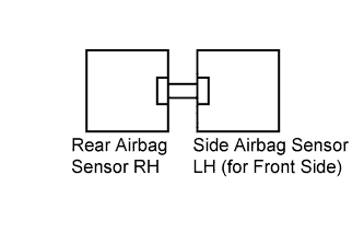
Interchange the rear airbag sensor RH with the rear airbag sensor LH and connect the connectors to them.
-
Connect the cable to the negative (-) battery terminal.
-
Turn the engine switch on (IG), and wait for at least 60 seconds.
-
Clear the DTCs stored in the memory (Click here).
-
Turn the engine switch off.
-
Turn the engine switch on (IG), and wait for at least 60 seconds.
-
Check for DTCs (Click here).
Result Result Proceed to DTC B1642, B1643, or 81 is output. A DTC B1647, B1648, or 82 is output. B DTCs B1642, B1643, or 81 and B1647, B1648, or 82 are not output. D Tip:Codes other than DTCs B1642, B1643, or 81 and B1647, B1648, or 82 may be output at this time, but they are not related to this check.
-
-
for RHD:
-
Turn the engine switch off.
-
Disconnect the cable from the negative (-) battery terminal, and wait for at least 90 seconds.
-
Return the side airbag sensor LH (for front side) and side airbag sensor RH (for front side) to their original positions and connect the connectors.
-
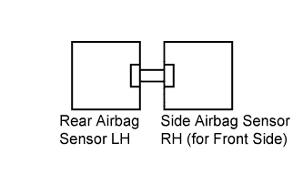
Interchange the rear airbag sensor LH with the rear airbag sensor RH and connect the connectors to them.
-
Connect the cable to the negative (-) battery terminal.
-
Turn the engine switch on (IG), and wait for at least 60 seconds.
-
Clear the DTCs stored in the memory (Click here).
-
Turn the engine switch off.
-
Turn the engine switch on (IG), and wait for at least 60 seconds.
-
Check for DTCs (Click here).
Result Result Proceed to DTC B1642, B1643, or 81 is output. A DTC B1647, B1648, or 82 is output. C DTCs B1642, B1643, or 81 and B1647, B1648, or 82 are not output. D Tip:Codes other than DTCs B1642, B1643, or 81 and B1647, B1648, or 82 may be output at this time, but they are not related to this check.
-
-
- Click here
CHECK DRIVER SIDE - SIDE AIRBAG SENSOR (FOR REAR SIDE)
-
for LHD:
-
Turn the engine switch off.
-
Disconnect the cable from the negative (-) battery terminal, and wait for at least 90 seconds.
-
Return the rear airbag sensor RH and rear airbag sensor LH to their original positions and connect the connectors.
-
Interchange the side airbag sensor RH (for rear side) with the side airbag sensor LH (for rear side) and connect the connectors.
-
Connect the cable to the negative (-) battery terminal.
-
Turn the engine switch on (IG), and wait for at least 60 seconds.
-
Clear the DTCs stored in the memory (Click here).
-
Turn the engine switch off.
-
Turn the engine switch on (IG), and wait for at least 60 seconds.
-
Check for DTCs (Click here).
Result Result Proceed to DTC B1642, B1643, or 81 is output. A DTC B1647, B1648, or 82 is output. B DTCs B1642, B1643, or 81 and B1647, B1648, or 82 are not output. D Tip:Codes other than DTCs B1642, B1643, or 81 and B1647, B1648, or 82 may be output at this time, but they are not related to this check.
-
-
for RHD:
-

Turn the engine switch off.
-
Disconnect the cable from the negative (-) battery terminal, and wait for at least 90 seconds.
-
Return the rear airbag sensor LH and rear airbag sensor RH to their original positions and connect the connectors.
-
Interchange the side airbag sensor LH (for rear side) with the side airbag sensor RH (for rear side) and connect the connectors.
-
Connect the cable to the negative (-) battery terminal.
-
Turn the engine switch on (IG), and wait for at least 60 seconds.
-
Clear the DTCs stored in the memory (Click here).
-
Turn the engine switch off.
-
Turn the engine switch on (IG), and wait for at least 60 seconds.
-
Check for DTCs (Click here).
Result Result Proceed to DTC B1642, B1643, or 81 is output. A DTC B1647, B1648, or 82 is output. C DTCs B1642, B1643, or 81 and B1647, B1648, or 82 are not output. D Tip:Codes other than DTCs B1642, B1643, or 81 and B1647, B1648, or 82 may be output at this time, but they are not related to this check.
-
-
- Click here
CHECK FLOOR AIRBAG SENSOR
-
for LHD:
-
Turn the engine switch off.
-
Disconnect the cable from the negative (-) battery terminal, and wait for at least 90 seconds.
-
Return the side airbag sensor RH (for rear side) and side airbag sensor LH (for rear side) to their original positions and connect the connectors.
-
Interchange the front floor airbag sensor with the rear floor airbag sensor and connect the connectors.
-
Connect the cable to the negative (-) battery terminal.
-
Turn the engine switch on (IG), and wait for at least 60 seconds.
-
Clear the DTCs stored in the memory (Click here).
-
Turn the engine switch off.
-
Turn the engine switch on (IG), and wait for at least 60 seconds.
-
Check for DTCs (Click here).
Result Result Proceed to DTC B1642, B1643, or 81 is output. A DTC B1647, B1648, or 82 is output. B DTCs B1642, B1643, or 81 and B1647, B1648, or 82 are not output. D Tip:Codes other than DTCs B1642, B1643, or 81 and B1647, B1648, or 82 may be output at this time, but they are not related to this check.
-
-
for RHD:
-
Turn the engine switch off.
-
Disconnect the cable from the negative (-) battery terminal, and wait for at least 90 seconds.
-
Return the side airbag sensor LH (for rear side) and side airbag sensor RH (for rear side) to their original positions and connect the connectors.
-
Interchange the rear floor airbag sensor with the front floor airbag sensor and connect the connectors.
-
Connect the cable to the negative (-) battery terminal.
-
Turn the engine switch on (IG), and wait for at least 60 seconds.
-
Clear the DTCs stored in the memory (Click here).
-
Turn the engine switch off.
-
Turn the engine switch on (IG), and wait for at least 60 seconds.
-
Check for DTCs (Click here).
Result Result Proceed to DTC B1642, B1643, or 81 is output. A DTC B1647, B1648, or 82 is output. C DTCs B1642, B1643, or 81 and B1647, B1648, or 82 are not output. D Tip:Codes other than DTCs B1642, B1643, or 81 and B1647, B1648, or 82 may be output at this time, but they are not related to this check.
-
-
- Click here
CHECK PAST DTC
-
Turn the engine switch on (IG), and wait for at least 60 seconds.
-
Check for past DTCs (Click here).
Result Result Proceed to Past DTCs B1622, B1632 and B1673 are not output. A Past DTC B1622 is output. B Past DTC B1632 is output. C Past DTC B1673 is output. D Tip:Codes other than past DTCs B1622, B1632 and B1673 may be output at this time, but they are not related to this check.
-
- Click here
CHECK PRESENT DTC
-
Turn the engine switch on (IG), and wait for at least 60 seconds.
-
Check for present DTCs (Click here).
Result Result Proceed to Present DTC B1623 is output. A Present DTC B1633 is output. B Present DTC B1674 is output. C Tip:Codes other than present DTCs B1623, B1633 and B1674 may be output at this time, but they are not related to this check.
-
- Click here
CHECK CONNECTORS
-
for LHD:
-
Turn the engine switch off.
-
Disconnect the cable from the negative (-) battery terminal, and wait for at least 90 seconds.
-
Check that the connectors are properly connected to the center airbag sensor assembly, side airbag sensor LH (for front side) and rear airbag sensor LH.
OK The connectors are properly connected. Tip:If the connectors are not connected securely, reconnect the connectors and proceed to the next inspection.
-
Disconnect the connectors from the center airbag sensor assembly, side airbag sensor LH (for front side) and rear airbag sensor LH.
-
Check that the terminals of the connectors are not damaged.
OK The terminals are not deformed or damaged. Table 25. Result Result Proceed to OK A NG B
-
-
for RHD:
-
Turn the engine switch off.
-
Disconnect the cable from the negative (-) battery terminal, and wait for at least 90 seconds.
-
Check that the connectors are properly connected to the center airbag sensor assembly, side airbag sensor RH (for front side) and rear airbag sensor RH.
OK The connectors are properly connected. Tip:If the connectors are not connected securely, reconnect the connectors and proceed to the next inspection.
-
Disconnect the connectors from the center airbag sensor assembly, side airbag sensor RH (for front side) and rear airbag sensor RH.
-
Check that the terminals of the connectors are not damaged.
OK The terminals are not deformed or damaged. Table 26. Result Result Proceed to OK A NG C
-
-
- Click here
CHECK WIRE HARNESS (OPEN)
-
for LHD:
-
Using SST, connect terminals 8 (BBD+) and 15 (BBD-) of connector B.
Note:Do not forcibly insert SST into the terminals of the connector when connecting.
-
Measure the resistance according to the value(s) in the table below.
Standard Resistance Tester Connection Condition Specified Condition N36-4 (BBL+) - N36-3 (BBL-) Always Below 1 Ω Table 27. Result Result Proceed to OK A NG B
09843-18040 -
-
for RHD:
-
Using SST, connect terminals 8 (BBD+) and 15 (BBD-) of connector B.
Note:Do not forcibly insert SST into the terminals of the connector when connecting.
-
Measure the resistance according to the value(s) in the table below.
Standard Resistance Tester Connection Condition Specified Condition M30-4 (BBR+) - M30-3 (BBR-) Always Below 1 Ω Table 28. Result Result Proceed to OK A NG C
09843-18040 -
-
- Click here
CHECK WIRE HARNESS (SHORT)
-
for LHD:
-
Disconnect SST from connector B.
-
Measure the resistance according to the value(s) in the table below.
Standard Resistance Tester Connection Condition Specified Condition N36-4 (BBL+) - N36-3 (BBL-) Always 1 MΩ or higher Table 29. Result Result Proceed to OK A NG B
-
-
for RHD:
-
Disconnect SST from connector B.
-
Measure the resistance according to the value(s) in the table below.
Standard Resistance Tester Connection Condition Specified Condition M30-4 (BBR+) - M30-3 (BBR-) Always 1 MΩ or higher Table 30. Result Result Proceed to OK A NG C
-
-
- Click here
CHECK WIRE HARNESS (SHORT TO B+)
-
for LHD:
-
Connect the cable to the negative (-) battery terminal.
-
Turn the engine switch on (IG).
-
Measure the voltage according to the value(s) in the table below.
Standard Voltage Tester Connection Switch Condition Specified Condition N36-4 (BBL+) - Body ground Engine switch on (IG) Below 1 V N36-3 (BBL-) - Body ground Engine switch on (IG) Below 1 V Table 31. Result Result Proceed to OK A NG B
-
-
for RHD:
-
Connect the cable to the negative (-) battery terminal.
-
Turn the engine switch on (IG).
-
Measure the voltage according to the value(s) in the table below.
Standard Voltage Tester Connection Switch Condition Specified Condition M30-4 (BBR+) - Body ground Engine switch on (IG) Below 1 V M30-3 (BBR-) - Body ground Engine switch on (IG) Below 1 V Table 32. Result Result Proceed to OK A NG C
-
-
- Click here
CHECK WIRE HARNESS (SHORT TO GROUND)
-
for LHD:
-
Turn the engine switch off.
-
Disconnect the cable from the negative (-) battery terminal, and wait for at least 90 seconds.
-
Measure the resistance according to the value(s) in the table below.
Standard Resistance Tester Connection Condition Specified Condition N36-4 (BBL+) - Body ground Always 1 MΩ or higher N36-3 (BBL-) - Body ground Always 1 MΩ or higher Table 33. Result Result Proceed to OK A NG B
-
-
for RHD:
-
Turn the engine switch off.
-
Disconnect the cable from the negative (-) battery terminal, and wait for at least 90 seconds.
-
Measure the resistance according to the value(s) in the table below.
Standard Resistance Tester Connection Condition Specified Condition M30-4 (BBR+) - Body ground Always 1 MΩ or higher M30-3 (BBR-) - Body ground Always 1 MΩ or higher Table 34. Result Result Proceed to OK A NG C
-
-
- Click here
CHECK WIRE HARNESS (OPEN)
-
for LHD:
-
Using SST, connect terminals 4 (BCL+) and 3 (BCL-) of connector C.
Note:Do not forcibly insert SST into the terminals of the connector when connecting.
-
Measure the resistance according to the value(s) in the table below.
Standard Resistance Tester Connection Condition Specified Condition N36-1 (BCL+) - N36-2 (BCL-) Always Below 1 Ω Table 35. Result Result Proceed to OK A NG B
09843-18040 -
-
for RHD:
-
Using SST, connect terminals 4 (BCR+) and 3 (BCR-) of connector C.
Note:Do not forcibly insert SST into the terminals of the connector when connecting.
-
Measure the resistance according to the value(s) in the table below.
Standard Resistance Tester Connection Condition Specified Condition M30-1 (BCR+) - M30-2 (BCR-) Always Below 1 Ω Table 36. Result Result Proceed to OK A NG C
09843-18040 -
-
- Click here
CHECK WIRE HARNESS (SHORT)
-
for LHD:
-
Disconnect SST from connector C.
-
Measure the resistance according to the value(s) in the table below.
Standard Resistance Tester Connection Condition Specified Condition N36-1 (BCL+) - N36-2 (BCL-) Always 1 MΩ or higher Table 37. Result Result Proceed to OK A NG B
-
-
for RHD:
-
Disconnect SST from connector C.
-
Measure the resistance according to the value(s) in the table below.
Standard Resistance Tester Connection Condition Specified Condition M30-1 (BCR+) - M30-2 (BCR-) Always 1 MΩ or higher Table 38. Result Result Proceed to OK A NG C
-
-
- Click here
CHECK WIRE HARNESS (SHORT TO B+)
-
for LHD:
-
Connect the cable to the negative (-) battery terminal.
-
Turn the engine switch on (IG).
-
Measure the voltage according to the value(s) in the table below.
Standard Voltage Tester Connection Switch Condition Specified Condition N36-1 (BCL+) - Body ground Engine switch on (IG) Below 1 V N36-2 (BCL-) - Body ground Engine switch on (IG) Below 1 V Table 39. Result Result Proceed to OK A NG B
-
-
for RHD:
-
Connect the cable to the negative (-) battery terminal.
-
Turn the engine switch on (IG).
-
Measure the voltage according to the value(s) in the table below.
Standard Voltage Tester Connection Switch Condition Specified Condition M30-1 (BCR+) - Body ground Engine switch on (IG) Below 1 V M30-2 (BCR-) - Body ground Engine switch on (IG) Below 1 V Table 40. Result Result Proceed to OK A NG C
-
-
- Click here
CHECK WIRE HARNESS (SHORT TO GROUND)
-
for LHD:
-
Turn the engine switch off.
-
Disconnect the cable from the negative (-) battery terminal, and wait for at least 90 seconds.
-
Measure the resistance according to the value(s) in the table below.
Standard Resistance Tester Connection Condition Specified Condition N36-1 (BCL+) - Body ground Always 1 MΩ or higher N36-2 (BCL-) - Body ground Always 1 MΩ or higher Table 41. Result Result Proceed to OK A NG B
-
-
for RHD:
-
Turn the engine switch off.
-
Disconnect the cable from the negative (-) battery terminal, and wait for at least 90 seconds.
-
Measure the resistance according to the value(s) in the table below.
Standard Resistance Tester Connection Condition Specified Condition M30-1 (BCR+) - Body ground Always 1 MΩ or higher M30-2 (BCR-) - Body ground Always 1 MΩ or higher Table 42. Result Result Proceed to OK A NG C
-
-
- Click here
CHECK DRIVER SIDE - SIDE AIRBAG SENSOR (FOR FRONT SIDE)
-
for LHD:
-
Connect the connectors to the rear airbag sensor LH and center airbag sensor assembly.
-
Interchange the side airbag sensor RH (for front side) with the side airbag sensor LH (for front side) and connect the connectors.
-
Connect the cable to the negative (-) battery terminal.
-
Turn the engine switch on (IG), and wait for at least 60 seconds.
-
Clear the DTCs stored in the memory (Click here).
-
Turn the engine switch off.
-
Turn the engine switch on (IG), and wait for at least 60 seconds.
-
Check for DTCs (Click here).
Result Result Proceed to DTC B1623 is output. A DTC B1628 is output. B DTCs B1623 and B1628 are not output. D Tip:Codes other than DTCs B1623 and B1628 may be output at this time, but they are not related to this check.
-
-
for RHD:
-
Connect the connectors to the rear airbag sensor RH and center airbag sensor assembly.
-
Interchange the side airbag sensor LH (for front side) with the side airbag sensor RH (for front side) and connect the connectors.
-
Connect the cable to the negative (-) battery terminal.
-
Turn the engine switch on (IG), and wait for at least 60 seconds.
-
Clear the DTCs stored in the memory (Click here).
-
Turn the engine switch off.
-
Turn the engine switch on (IG), and wait for at least 60 seconds.
-
Check for DTCs (Click here).
Result Result Proceed to DTC B1623 is output. A DTC B1628 is output. C DTCs B1623 and B1628 are not output. D Tip:Codes other than DTCs B1623 and B1628 may be output at this time, but they are not related to this check.
-
-
- Click here
CHECK DRIVER SIDE REAR AIRBAG SENSOR
-
for LHD:
-
Turn the engine switch off.
-
Disconnect the cable from the negative (-) battery terminal, and wait for at least 90 seconds.
-
Return the side airbag sensor RH (for front side) and side airbag sensor LH (for front side) to their original positions and connect the connectors.
-
Interchange the rear airbag sensor RH with the rear airbag sensor LH and connect the connectors.
-
Connect the cable to the negative (-) battery terminal.
-
Turn the engine switch on (IG), and wait for at least 60 seconds.
-
Clear the DTCs stored in the memory (Click here).
-
Turn the engine switch off.
-
Turn the engine switch on (IG), and wait for at least 60 seconds.
-
Check for DTCs (Click here).
Result Result Proceed to DTC B1623 is output. A DTC B1628 is output. B DTCs B1623 and B1628 are not output. D Tip:Codes other than DTCs B1623 and B1628 may be output at this time, but they are not related to this check.
-
-
for RHD:
-
Turn the engine switch off.
-
Disconnect the cable from the negative (-) battery terminal, and wait for at least 90 seconds.
-
Return the side airbag sensor LH (for front side) and side airbag sensor RH (for front side) to their original positions and connect the connectors.
-
Interchange the rear airbag sensor LH with the rear airbag sensor RH and connect the connectors.
-
Connect the cable to the negative (-) battery terminal.
-
Turn the engine switch on (IG), and wait for at least 60 seconds.
-
Clear the DTCs stored in the memory (Click here).
-
Turn the engine switch off.
-
Turn the engine switch on (IG), and wait for at least 60 seconds.
-
Check for DTCs (Click here).
Result Result Proceed to DTC B1623 is output. A DTC B1628 is output. C DTCs B1623 and B1628 are not output. D Tip:Codes other than DTCs B1623 and B1628 may be output at this time, but they are not related to this check.
-
-
- Click here
CHECK CONNECTORS
-
for LHD:
-
Turn the engine switch off.
-
Disconnect the cable from the negative (-) battery terminal, and wait for at least 90 seconds.
-
Check that the connectors are properly connected to the side airbag sensor LH (for front side), rear airbag sensor LH and side airbag sensor LH (for rear side). Also check that the connectors that link the No. 2 floor wire and No. 2 rear door wire are properly connected.
OK The connectors are properly connected. Tip:If the connectors are not connected securely, reconnect the connectors and proceed to the next inspection.
-
Disconnect the connectors from the side airbag sensor LH (for front side), rear airbag sensor LH and side airbag sensor LH (for rear side). Also disconnect the connectors that link the No. 2 floor wire and No. 2 rear door wire.
-
Check that the terminals of the connectors are not damaged.
OK The terminals are not deformed or damaged.
-
-
for RHD:
-
Turn the engine switch off.
-
Disconnect the cable from the negative (-) battery terminal, and wait for at least 90 seconds.
-
Check that the connectors are properly connected to the side airbag sensor RH (for front side), rear airbag sensor RH and side airbag sensor RH (for rear side). Also check that the connectors that link the floor wire and No. 1 rear door wire are properly connected.
OK The connectors are properly connected. Tip:If the connectors are not connected securely, reconnect the connectors and proceed to the next inspection.
-
Disconnect the connectors from the side airbag sensor RH (for front side), rear airbag sensor RH and side airbag sensor RH (for rear side). Also disconnect the connectors that link the floor wire and No. 1 rear door wire.
-
Check that the terminals of the connectors are not damaged.
OK The terminals are not deformed or damaged.
-
- OKClick here
- NGClick here
-
- Click here
CHECK WIRE HARNESS (OPEN)
-
for LHD:
-
Using SST, connect terminals 4 (BCL+) and 3 (BCL-) of connector C.
Note:Do not forcibly insert SST into the terminals of the connector when connecting.
-
Measure the resistance according to the value(s) in the table below.
Standard Resistance Tester Connection Condition Specified Condition N36-1 (BCL+) - N36-2 (BCL-) Always Below 1 Ω Table 43. Result Result Proceed to OK A NG B
09843-18040 -
-
for RHD:
-
Using SST, connect terminals 4 (BCR+) and 3 (BCR-) of connector C.
Note:Do not forcibly insert SST into the terminals of the connector when connecting.
-
Measure the resistance according to the value(s) in the table below.
Standard Resistance Tester Connection Condition Specified Condition M30-1 (BCR+) - M30-2 (BCR-) Always Below 1 Ω Table 44. Result Result Proceed to OK A NG C
09843-18040 -
-
- Click here
CHECK WIRE HARNESS (SHORT)
-
for LHD:
-
Disconnect SST from connector C.
-
Measure the resistance according to the value(s) in the table below.
Standard Resistance Tester Connection Condition Specified Condition N36-1 (BCL+) - N36-2 (BCL-) Always 1 MΩ or higher Table 45. Result Result Proceed to OK A NG B
-
-
for RHD:
-
Disconnect SST from connector C.
-
Measure the resistance according to the value(s) in the table below.
Standard Resistance Tester Connection Condition Specified Condition M30-1 (BCR+) - M30-2 (BCR-) Always 1 MΩ or higher Table 46. Result Result Proceed to OK A NG C
-
-
- Click here
CHECK WIRE HARNESS (SHORT TO B+)
-
for LHD:
-
Connect the cable to the negative (-) battery terminal.
-
Turn the engine switch on (IG).
-
Measure the voltage according to the value(s) in the table below.
Standard Voltage Tester Connection Switch Condition Specified Condition N36-1 (BCL+) - Body ground Engine switch on (IG) Below 1 V N36-2 (BCL-) - Body ground Engine switch on (IG) Below 1 V Table 47. Result Result Proceed to OK A NG B
-
-
for RHD:
-
Connect the cable to the negative (-) battery terminal.
-
Turn the engine switch on (IG).
-
Measure the voltage according to the value(s) in the table below.
Standard Voltage Tester Connection Switch Condition Specified Condition M30-1 (BCR+) - Body ground Engine switch on (IG) Below 1 V M30-2 (BCR-) - Body ground Engine switch on (IG) Below 1 V Table 48. Result Result Proceed to OK A NG C
-
-
- Click here
CHECK WIRE HARNESS (SHORT TO GROUND)
-
for LHD:
-
Turn the engine switch off.
-
Disconnect the cable from the negative (-) battery terminal, and wait for at least 90 seconds.
-
Measure the resistance according to the value(s) in the table below.
Standard Resistance Tester Connection Condition Specified Condition N36-1 (BCL+) - Body ground Always 1 MΩ or higher N36-2 (BCL-) - Body ground Always 1 MΩ or higher Table 49. Result Result Proceed to OK A NG B
-
-
for RHD:
-
Turn the engine switch off.
-
Disconnect the cable from the negative (-) battery terminal, and wait for at least 90 seconds.
-
Measure the resistance according to the value(s) in the table below.
Standard Resistance Tester Connection Condition Specified Condition M30-1 (BCR+) - Body ground Always 1 MΩ or higher M30-2 (BCR-) - Body ground Always 1 MΩ or higher Table 50. Result Result Proceed to OK A NG C
-
-
- Click here
CHECK WIRE HARNESS (OPEN)
-
for LHD:
-
Connect the connectors that link the No. 2 floor wire and No. 2 rear door wire.
-
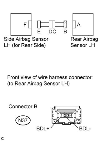
Using SST, connect terminals 4 (BDL+) and 3 (BDL-) of connector E.
Note:Do not forcibly insert SST into the terminals of the connector when connecting.
-
Measure the resistance according to the value(s) in the table below.
Standard Resistance Tester Connection Condition Specified Condition N37-1 (BDL+) - N37-2 (BDL-) Always Below 1 Ω
09843-18040 -
-
for RHD:
-
Connect the connectors that link the floor wire and No. 1 rear door wire.
-
Using SST, connect terminals 4 (BDR+) and 3 (BDR-) of connector E.
Note:Do not forcibly insert SST into the terminals of the connector when connecting.
-
Measure the resistance according to the value(s) in the table below.
Standard Resistance Tester Connection Condition Specified Condition M31-1 (BDR+) - M31-2 (BDR-) Always Below 1 Ω
09843-18040 -
- OKClick here
- NGClick here
-
- Click here
CHECK WIRE HARNESS (SHORT)
-
for LHD:
-
Disconnect SST from connector E.
-
Measure the resistance according to the value(s) in the table below.
Standard Resistance Tester Connection Condition Specified Condition N37-1 (BDL+) - N37-2 (BDL-) Always 1 MΩ or higher
-
-
for RHD:
-
Disconnect SST from connector E.
-
Measure the resistance according to the value(s) in the table below.
Standard Resistance Tester Connection Condition Specified Condition M31-1 (BDR+) - M31-2 (BDR-) Always 1 MΩ or higher
-
- OKClick here
- NGClick here
-
- Click here
CHECK WIRE HARNESS (SHORT TO B+)
-
for LHD:
-
Connect the cable to the negative (-) battery terminal.
-
Turn the engine switch on (IG).
-
Measure the voltage according to the value(s) in the table below.
Standard Voltage Tester Connection Switch Condition Specified Condition N37-1 (BDL+) - Body ground Engine switch on (IG) Below 1 V N37-2 (BDL-) - Body ground Engine switch on (IG) Below 1 V
-
-
for RHD:
-
Connect the cable to the negative (-) battery terminal.
-
Turn the engine switch on (IG).
-
Measure the voltage according to the value(s) in the table below.
Standard Voltage Tester Connection Switch Condition Specified Condition M31-1 (BDR+) - Body ground Engine switch on (IG) Below 1 V M31-2 (BDR-) - Body ground Engine switch on (IG) Below 1 V
-
- OKClick here
- NGClick here
-
- Click here
CHECK WIRE HARNESS (SHORT TO GROUND)
-
for LHD:
-
Turn the engine switch off.
-
Disconnect the cable from the negative (-) battery terminal, and wait for at least 90 seconds.
-
Measure the resistance according to the value(s) in the table below.
Standard Resistance Tester Connection Condition Specified Condition N37-1 (BDL+) - Body ground Always 1 MΩ or higher N37-2 (BDL-) - Body ground Always 1 MΩ or higher
-
-
for RHD:
-
Turn the engine switch off.
-
Disconnect the cable from the negative (-) battery terminal, and wait for at least 90 seconds.
-
Measure the resistance according to the value(s) in the table below.
Standard Resistance Tester Connection Condition Specified Condition M31-1 (BDR+) - Body ground Always 1 MΩ or higher M31-2 (BDR-) - Body ground Always 1 MΩ or higher
-
- OKClick here
- NGClick here
-
- Click here
CHECK DRIVER SIDE REAR AIRBAG SENSOR
-
for LHD:
-
Connect the connector to the side airbag sensor LH (for front side) and side airbag sensor LH (for rear side).
-
Interchange the rear airbag sensor RH with the rear airbag sensor LH and connect the connectors.
-
Connect the cable to the negative (-) battery terminal.
-
Turn the engine switch on (IG), and wait for at least 60 seconds.
-
Clear the DTCs stored in the memory (Click here).
-
Turn the engine switch off.
-
Turn the engine switch on (IG), and wait for at least 60 seconds.
-
Check for DTCs (Click here).
Result Result Proceed to DTC B1633 is output. A DTC B1638 is output. B DTCs B1633 and B1638 are not output. D Tip:Codes other than DTCs B1633 and B1638 may be output at this time, but they are not related to this check.
-
-
for RHD:
-
Connect the connector to the side airbag sensor RH (for front side) and side airbag sensor RH (for rear side).
-
Interchange the rear airbag sensor LH with the rear airbag sensor RH and connect the connectors.
-
Connect the cable to the negative (-) battery terminal.
-
Turn the engine switch on (IG), and wait for at least 60 seconds.
-
Clear the DTCs stored in the memory (Click here).
-
Turn the engine switch off.
-
Turn the engine switch on (IG), and wait for at least 60 seconds.
-
Check for DTCs (Click here).
Result Result Proceed to DTC B1633 is output. A DTC B1638 is output. C DTCs B1633 and B1638 are not output. D Tip:Codes other than DTCs B1633 and B1638 may be output at this time, but they are not related to this check.
-
-
- Click here
CHECK DRIVER SIDE - SIDE AIRBAG SENSOR (FOR REAR SIDE)
-
for LHD:
-
Turn the engine switch off.
-
Disconnect the cable from the negative (-) battery terminal, and wait for at least 90 seconds.
-
Return the rear airbag sensor RH and rear airbag sensor LH to their original positions and connect the connectors.
-
Interchange the side airbag sensor RH (for rear side) with side airbag sensor LH (for rear side) and connect the connectors.
-
Connect the cable to the negative (-) battery terminal.
-
Turn the engine switch on (IG), and wait for at least 60 seconds.
-
Clear the DTCs stored in the memory (Click here).
-
Turn the engine switch off.
-
Turn the engine switch on (IG), and wait for at least 60 seconds.
-
Check for DTCs (Click here).
Result Result Proceed to DTC B1633 is output. A DTC B1638 is output. B DTCs B1633 and B1638 are not output. D Tip:Codes other than DTCs B1633 and B1638 may be output at this time, but they are not related to this check.
-
-
for RHD:
-
Turn the engine switch off.
-
Disconnect the cable from the negative (-) battery terminal, and wait for at least 90 seconds.
-
Return the rear airbag sensor LH and rear airbag sensor RH to their original positions and connect the connectors.
-
Interchange the side airbag sensor LH (for rear side) with the side airbag sensor RH (for rear side) and connect the connectors.
-
Connect the cable to the negative (-) battery terminal.
-
Turn the engine switch on (IG), and wait for at least 60 seconds.
-
Clear the DTCs stored in the memory (Click here).
-
Turn the engine switch off.
-
Turn the engine switch on (IG), and wait for at least 60 seconds.
-
Check for DTCs (Click here).
Result Result Proceed to DTC B1633 is output. A DTC B1638 is output. C DTCs B1633 and B1638 are not output. D Tip:Codes other than DTCs B1633 and B1638 may be output at this time, but they are not related to this check.
-
-
- Click here
CHECK DRIVER SIDE - SIDE AIRBAG SENSOR (FOR FRONT SIDE)
-
for LHD:
-
Turn the engine switch off.
-
Disconnect the cable from the negative (-) battery terminal, and wait for at least 90 seconds.
-
Return the side airbag sensor RH (for rear side) and side airbag sensor LH (for rear side) to their original positions and connect the connectors.
-
Interchange the side airbag sensor RH (for front side) with the side airbag sensor LH (for front side) and connect the connectors.
-
Connect the cable to the negative (-) battery terminal.
-
Turn the engine switch on (IG), and wait for at least 60 seconds.
-
Clear the DTCs stored in the memory (Click here).
-
Turn the engine switch off.
-
Turn the engine switch on (IG), and wait for at least 60 seconds.
-
Check for DTCs (Click here).
Result Result Proceed to DTC B1633 is output. A DTC B1638 is output. B DTCs B1633 and B1638 are not output. D Tip:Codes other than DTCs B1633 and B1638 may be output at this time, but they are not related to this check.
-
-
for RHD:
-
Turn the engine switch off.
-
Disconnect the cable from the negative (-) battery terminal, and wait for at least 90 seconds.
-
Return the side airbag sensor LH (for rear side) and side airbag sensor RH (for rear side) to their original positions and connect the connectors.
-
Interchange the side airbag sensor LH (for front side) with the side airbag sensor RH (for front side) and connect the connectors.
-
Connect the cable to the negative (-) battery terminal.
-
Turn the engine switch on (IG), and wait for at least 60 seconds.
-
Clear the DTCs stored in the memory (Click here).
-
Turn the engine switch off.
-
Turn the engine switch on (IG), and wait for at least 60 seconds.
-
Check for DTCs (Click here).
Result Result Proceed to DTC B1633 is output. A DTC B1638 is output. C DTCs B1633 and B1638 are not output. D Tip:Codes other than DTCs B1633 and B1638 may be output at this time, but they are not related to this check.
-
-
- Click here
CHECK CONNECTORS
-
for LHD:
-
Turn the engine switch off.
-
Disconnect the cable from the negative (-) battery terminal, and wait for at least 90 seconds.
-
Check that the connectors are properly connected to the rear airbag sensor LH, side airbag sensor LH (for rear side) and rear floor airbag sensor. Also check that the connectors that link the No. 2 floor wire and No. 2 rear door wire are properly connected.
OK The connectors are properly connected. Tip:If the connectors are not connected securely, reconnect the connectors and proceed to the next inspection.
-
Disconnect the connectors from the rear airbag sensor LH, side airbag sensor LH (for rear side) and rear floor airbag sensor. Also disconnect the connectors that link the No. 2 floor wire and No. 2 rear door wire.
-
Check that the terminals of the connectors are not damaged.
OK The terminals are not deformed or damaged.
-
-
for RHD:
-
Turn the engine switch off.
-
Disconnect the cable from the negative (-) battery terminal, and wait for at least 90 seconds.
-
Check that the connectors are properly connected to the rear airbag sensor RH, side airbag sensor RH (for rear side) and front floor airbag sensor. Also check that the connectors that link the floor wire, No. 2 floor wire and No. 1 rear door wire are properly connected.
OK The connectors are properly connected. Tip:If the connectors are not connected securely, reconnect the connectors and proceed to the next inspection.
-
Disconnect the connectors from the rear airbag sensor RH, side airbag sensor RH (for rear side) and front floor airbag sensor. Also disconnect the connectors that link the floor wire, No. 2 floor wire and No. 1 rear door wire.
-
Check that the terminals of the connectors are not damaged.
OK The terminals are not deformed or damaged.
-
- OKClick here
- NGClick here
-
- Click here
CHECK WIRE HARNESS (OPEN)
-
for LHD:
-
Connect the connectors that link the No. 2 floor wire and No. 2 rear door wire.
-
Using SST, connect terminals 4 (BDL+) and 3 (BDL-) of connector E.
Note:Do not forcibly insert SST into the terminals of the connector when connecting.
-
Measure the resistance according to the value(s) in the table below.
Standard Resistance Tester Connection Condition Specified Condition N37-1 (BDL+) - N37-2 (BDL-) Always Below 1 Ω
09843-18040 -
-
for RHD:
-
Connect the connectors that link the floor wire and No. 1 rear door wire.
-
Using SST, connect terminals 4 (BDR+) and 3 (BDR-) of connector E.
Note:Do not forcibly insert SST into the terminals of the connector when connecting.
-
Measure the resistance according to the value(s) in the table below.
Standard Resistance Tester Connection Condition Specified Condition M31-1 (BDR+) - M31-2 (BDR-) Always Below 1 Ω
09843-18040 -
- OKClick here
- NGClick here
-
- Click here
CHECK WIRE HARNESS (SHORT)
-
for LHD:
-
Disconnect SST from connector E.
-
Measure the resistance according to the value(s) in the table below.
Standard Resistance Tester Connection Condition Specified Condition N37-1 (BDL+) - N37-2 (BDL-) Always 1 MΩ or higher
-
-
for RHD:
-
Disconnect SST from connector E.
-
Measure the resistance according to the value(s) in the table below.
Standard Resistance Tester Connection Condition Specified Condition M31-1 (BDR+) - M31-2 (BDR-) Always 1 MΩ or higher
-
- OKClick here
- NGClick here
-
- Click here
CHECK WIRE HARNESS (SHORT TO B+)
-
for LHD:
-
Connect the cable to the negative (-) battery terminal.
-
Turn the engine switch on (IG).
-
Measure the voltage according to the value(s) in the table below.
Standard Voltage Tester Connection Switch Condition Specified Condition N37-1 (BDL+) - Body ground Engine switch on (IG) Below 1 V N37-2 (BDL-) - Body ground Engine switch on (IG) Below 1 V
-
-
for RHD:
-
Connect the cable to the negative (-) battery terminal.
-
Turn the engine switch on (IG).
-
Measure the voltage according to the value(s) in the table below.
Standard Voltage Tester Connection Switch Condition Specified Condition M31-1 (BDR+) - Body ground Engine switch on (IG) Below 1 V M31-2 (BDR-) - Body ground Engine switch on (IG) Below 1 V
-
- OKClick here
- NGClick here
-
- Click here
CHECK WIRE HARNESS (SHORT TO GROUND)
-
for LHD:
-
Turn the engine switch off.
-
Disconnect the cable from the negative (-) battery terminal, and wait for at least 90 seconds.
-
Measure the resistance according to the value(s) in the table below.
Standard Resistance Tester Connection Condition Specified Condition N37-1 (BDL+) - Body ground Always 1 MΩ or higher N37-2 (BDL-) - Body ground Always 1 MΩ or higher
-
-
for RHD:
-
Turn the engine switch off.
-
Disconnect the cable from the negative (-) battery terminal, and wait for at least 90 seconds.
-
Measure the resistance according to the value(s) in the table below.
Standard Resistance Tester Connection Condition Specified Condition M31-1 (BDR+) - Body ground Always 1 MΩ or higher M31-2 (BDR-) - Body ground Always 1 MΩ or higher
-
- OKClick here
- NGClick here
-
- Click here
CHECK WIRE HARNESS (OPEN)
-
for LHD:
-
Connect the connectors that link the No. 2 floor wire and No. 2 rear door wire.
-
Using SST, connect terminals 2 (BEL+) and 1 (BEL-) of connector E.
Note:Do not forcibly insert SST into the terminals of the connector when connecting.
-
Measure the resistance according to the value(s) in the table below.
Standard Resistance Tester Connection Condition Specified Condition L9-1 (BEL+) - L9-2 (BEL-) Always Below 1 Ω Table 51. Result Result Proceed to OK A NG B
09843-18040 -
-
for RHD:
-
Connect the connectors that link the floor wire, No. 2 floor wire and No. 1 rear door wire.
-
Using SST, connect terminals 2 (BER+) and 1 (BER-) of connector G.
Note:Do not forcibly insert SST into the terminals of the connector when connecting.
-
Measure the resistance according to the value(s) in the table below.
Standard Resistance Tester Connection Condition Specified Condition K9-1 (BER+) - K9-2 (BER-) Always Below 1 Ω Table 52. Result Result Proceed to OK A NG C
09843-18040 -
-
- Click here
CHECK WIRE HARNESS (SHORT)
-
for LHD:
-
Disconnect SST from connector E.
-
Measure the resistance according to the value(s) in the table below.
Standard Resistance Tester Connection Condition Specified Condition L9-1 (BEL+) - L9-2 (BEL-) Always 1 MΩ or higher Table 53. Result Result Proceed to OK A NG B
-
-
for RHD:
-
Disconnect SST from connector G.
-
Measure the resistance according to the value(s) in the table below.
Standard Resistance Tester Connection Condition Specified Condition K9-1 (BER+) - K9-2 (BER-) Always 1 MΩ or higher Table 54. Result Result Proceed to OK A NG C
-
-
- Click here
CHECK WIRE HARNESS (SHORT TO B+)
-
for LHD:
-
Connect the cable to the negative (-) battery terminal.
-
Turn the engine switch on (IG).
-
Measure the voltage according to the value(s) in the table below.
Standard Voltage Tester Connection Switch Condition Specified Condition L9-1 (BEL+) - Body ground Engine switch on (IG) Below 1 V L9-2 (BEL-) - Body ground Engine switch on (IG) Below 1 V Table 55. Result Result Proceed to OK A NG B
-
-
for RHD:
-
Connect the cable to the negative (-) battery terminal.
-
Turn the engine switch on (IG).
-
Measure the voltage according to the value(s) in the table below.
Standard Voltage Tester Connection Switch Condition Specified Condition K9-1 (BER+) - Body ground Engine switch on (IG) Below 1 V K9-2 (BER-) - Body ground Engine switch on (IG) Below 1 V Table 56. Result Result Proceed to OK A NG C
-
-
- Click here
CHECK WIRE HARNESS (SHORT TO GROUND)
-
for LHD:
-
Turn the engine switch off.
-
Disconnect the cable from the negative (-) battery terminal, and wait for at least 90 seconds.
-
Measure the resistance according to the value(s) in the table below.
Standard Resistance Tester Connection Condition Specified Condition L9-1 (BEL+) - Body ground Always 1 MΩ or higher L9-2 (BEL-) - Body ground Always 1 MΩ or higher Table 57. Result Result Proceed to OK A NG B
-
-
for RHD:
-
Turn the engine switch off.
-
Disconnect the cable from the negative (-) battery terminal, and wait for at least 90 seconds.
-
Measure the resistance according to the value(s) in the table below.
Standard Resistance Tester Connection Condition Specified Condition K9-1 (BER+) - Body ground Always 1 MΩ or higher K9-2 (BER-) - Body ground Always 1 MΩ or higher Table 58. Result Result Proceed to OK A NG C
-
-
- Click here
CHECK DRIVER SIDE - SIDE AIRBAG SENSOR (FOR REAR SIDE)
-
for LHD:
-
Connect the connectors to the rear airbag sensor LH and rear floor airbag sensor.
-
Interchange the side airbag sensor RH (for rear side) with the side airbag sensor LH (for rear side) and connect the connectors.
-
Connect the cable to the negative (-) battery terminal.
-
Turn the engine switch on (IG), and wait for at least 60 seconds.
-
Clear the DTCs stored in the memory (Click here).
-
Turn the engine switch off.
-
Turn the engine switch on (IG), and wait for at least 60 seconds.
-
Check for DTCs (Click here).
Result Result Proceed to DTC B1674 is output. A DTC B1689 is output. B DTCs B1674 and B1689 are not output. D Tip:Codes other than DTCs B1674 and B1689 may be output at this time, but they are not related to this check.
-
-
for RHD:
-
Connect the connectors to the rear airbag sensor RH and front floor airbag sensor.
-
Interchange the side airbag sensor LH (for rear side) with the side airbag sensor RH (for rear side) and connect the connectors.
-
Connect the cable to the negative (-) battery terminal.
-
Turn the engine switch on (IG), and wait for at least 60 seconds.
-
Clear the DTCs stored in the memory (Click here).
-
Turn the engine switch off.
-
Turn the engine switch on (IG), and wait for at least 60 seconds.
-
Check for DTCs (Click here).
Result Result Proceed to DTC B1674 is output. A DTC B1689 is output. C DTCs B1674 and B1689 are not output. D Tip:Codes other than DTCs B1674 and B1689 may be output at this time, but they are not related to this check.
-
-
- Click here
CHECK FLOOR AIRBAG SENSOR
-
for LHD:
-
Turn the engine switch off.
-
Disconnect the cable from the negative (-) battery terminal, and wait for at least 90 seconds.
-
Return the side airbag sensor RH (for rear side) and side airbag sensor LH (for rear side) to their original positions and connect the connectors.
-
Interchange the front floor airbag sensor with the rear floor airbag sensor and connect the connectors.
-
Connect the cable to the negative (-) battery terminal.
-
Turn the engine switch on (IG), and wait for at least 60 seconds.
-
Clear the DTCs stored in the memory (Click here).
-
Turn the engine switch off.
-
Turn the engine switch on (IG), and wait for at least 60 seconds.
-
Check for DTCs (Click here).
Result Result Proceed to DTC B1674 is output. A DTC B1689 is output. B DTCs B1674 and B1689 are not output. D Tip:Codes other than DTCs B1674 and B1689 may be output at this time, but they are not related to this check.
-
-
for RHD:
-
Turn the engine switch off.
-
Disconnect the cable from the negative (-) battery terminal, and wait for at least 90 seconds.
-
Return the side airbag sensor LH (for rear side) and side airbag sensor RH (for rear side) to their original positions and connect the connectors.
-
Interchange the rear floor airbag sensor with the front floor airbag sensor and connect the connectors.
-
Connect the cable to the negative (-) battery terminal.
-
Turn the engine switch on (IG), and wait for at least 60 seconds.
-
Clear the DTCs stored in the memory (Click here).
-
Turn the engine switch off.
-
Turn the engine switch on (IG), and wait for at least 60 seconds.
-
Check for DTCs (Click here).
Result Result Proceed to DTC B1674 is output. A DTC B1689 is output. C DTCs B1674 and B1689 are not output. D Tip:Codes other than DTCs B1674 and B1689 may be output at this time, but they are not related to this check.
-
-
- Click here
CHECK DRIVER SIDE REAR AIRBAG SENSOR
-
for LHD:
-
Turn the engine switch off.
-
Disconnect the cable from the negative (-) battery terminal, and wait for at least 90 seconds.
-
Return the front floor airbag sensor and rear floor airbag sensor to their original positions and connect the connectors.
-
Interchange the rear airbag sensor RH with the rear airbag sensor LH and connect the connectors to them.
-
Connect the cable to the negative (-) battery terminal.
-
Turn the engine switch on (IG), and wait for at least 60 seconds.
-
Clear the DTCs stored in the memory (Click here).
-
Turn the engine switch off.
-
Turn the engine switch on (IG), and wait for at least 60 seconds.
-
Check for DTCs (Click here).
Result Result Proceed to DTC B1674 is output. A DTC B1689 is output. B DTCs B1674 and B1689 are not output. D Tip:Codes other than DTCs B1674 and B1689 may be output at this time, but they are not related to this check.
-
-
for RHD:
-
Turn the engine switch off.
-
Disconnect the cable from the negative (-) battery terminal, and wait for at least 90 seconds.
-
Return the rear floor airbag sensor and front floor airbag sensor to their original positions and connect the connectors.
-
Interchange the rear airbag sensor LH with the rear airbag sensor RH and connect the connectors to them.
-
Connect the cable to the negative (-) battery terminal.
-
Turn the engine switch on (IG), and wait for at least 60 seconds.
-
Clear the DTCs stored in the memory (Click here).
-
Turn the engine switch off.
-
Turn the engine switch on (IG), and wait for at least 60 seconds.
-
Check for DTCs (Click here).
Result Result Proceed to DTC B1674 is output. A DTC B1689 is output. C DTCs B1674 and B1689 are not output. D Tip:Codes other than DTCs B1674 and B1689 may be output at this time, but they are not related to this check.
-
-
- Click here
CHECK PRESENT DTC
-
Turn the engine switch on (IG), and wait for at least 60 seconds.
-
Check for present DTCs (Click here).
Result Result Proceed to Present DTC B1676 or B1677 is output. A Present DTC B1666 or B1667 is output. B Tip:Codes other than present DTCs B1666, B1667, B1676 and B1677 may be output at this time, but they are not related to this check.
-
- Click here
CHECK CONNECTORS
-
Turn the engine switch off.
-
Disconnect the cable from the negative (-) battery terminal, and wait for at least 90 seconds.
-
Check that the connectors are properly connected to the side airbag sensor LH (for rear side) and rear floor airbag sensor. Also check that the connectors that link the No. 2 floor wire and No. 2 rear door wire are properly connected.
OK The connectors are properly connected. Tip:If the connectors are not connected securely, reconnect the connectors and proceed to the next inspection.
-
Disconnect the connectors from the side airbag sensor LH (for rear side) and rear floor airbag sensor. Also disconnect the connectors that link the No. 2 floor wire and No. 2 rear door wire.
-
Check that the terminals of the connectors are not damaged.
OK The terminals are not deformed or damaged.
- OKClick here
- NGClick here
-
- Click here
CHECK WIRE HARNESS (OPEN)
-
Connect the connectors that link the No. 2 floor wire and No. 2 rear door wire.
-
Using SST, connect terminals 2 (BEL+) and 1 (BEL-) of connector E.
Note:Do not forcibly insert SST into the terminals of the connector when connecting.
09843-18040 -
Measure the resistance according to the value(s) in the table below.
Standard Resistance Tester Connection Condition Specified Condition L9-1 (BEL+) - L9-2 (BEL-) Always Below 1 Ω
- OKClick here
- NGClick here
-
- Click here
CHECK WIRE HARNESS (SHORT)
-
Disconnect SST from connector E.
-
Measure the resistance according to the value(s) in the table below.
Standard Resistance Tester Connection Condition Specified Condition L9-1 (BEL+) - L9-2 (BEL-) Always 1 MΩ or higher
- OKClick here
- NGClick here
-
- Click here
CHECK WIRE HARNESS (SHORT TO B+)
-
Connect the cable to the negative (-) battery terminal.
-
Turn the engine switch on (IG).
-
Measure the voltage according to the value(s) in the table below.
Standard Voltage Tester Connection Switch Condition Specified Condition L9-1 (BEL+) - Body ground Engine switch on (IG) Below 1 V L9-2 (BEL-) - Body ground Engine switch on (IG) Below 1 V
- OKClick here
- NGClick here
-
- Click here
CHECK WIRE HARNESS (SHORT TO GROUND)
-
Turn the engine switch off.
-
Disconnect the cable from the negative (-) battery terminal, and wait for at least 90 seconds.
-
Measure the resistance according to the value(s) in the table below.
Standard Resistance Tester Connection Condition Specified Condition L9-1 (BEL+) - Body ground Always 1 MΩ or higher L9-2 (BEL-) - Body ground Always 1 MΩ or higher
- OKClick here
- NGClick here
-
- Click here
CHECK REAR FLOOR AIRBAG SENSOR
-
Connect the connector to the side airbag sensor LH (for rear side).
-
Interchange the front floor airbag sensor with the rear floor airbag sensor and connect the connectors.
-
Connect the cable to the negative (-) battery terminal.
-
Turn the engine switch on (IG), and wait for at least 60 seconds.
-
Clear the DTCs stored in the memory (Click here).
-
Turn the engine switch off.
-
Turn the engine switch on (IG), and wait for at least 60 seconds.
-
Check for DTCs (Click here).
Result Result Proceed to DTC B1676 or B1677 is output. A DTC B1668 or B1669 is output. B DTCs B1668, B1669, B1676 and B1677 are not output. C Tip:Codes other than DTCs B1668, B1669, B1676 and B1677 may be output at this time, but they are not related to this check.
-
- Click here
CHECK SIDE AIRBAG SENSOR LH (FOR REAR SIDE)
-
Turn the engine switch off.
-
Disconnect the cable from the negative (-) battery terminal, and wait for at least 90 seconds.
-
Return the front floor airbag sensor and rear floor airbag sensor to their original positions and connect the connectors.
-
Interchange the side airbag sensor RH (for rear side) with the side airbag sensor LH (for rear side) and connect the connectors.
-
Connect the cable to the negative (-) battery terminal.
-
Turn the engine switch on (IG), and wait for at least 60 seconds.
-
Clear the DTCs stored in the memory (Click here).
-
Turn the engine switch off.
-
Turn the engine switch on (IG), and wait for at least 60 seconds.
-
Check for DTCs (Click here).
Result Result Proceed to DTC B1676 or B1677 is output. A DTC B1668 or B1669 is output. B DTCs B1668, B1669, B1676 and B1677 are not output. C Tip:Codes other than DTCs B1668, B1669, B1676 and B1677 may be output at this time, but they are not related to this check.
-
- Click here
CHECK CONNECTORS
-
Turn the engine switch off.
-
Disconnect the cable from the negative (-) battery terminal, and wait for at least 90 seconds.
-
Check that the connectors are properly connected to the side airbag sensor RH (for rear side) and front floor airbag sensor. Also check that the connectors that link the floor wire, No. 2 floor wire and No. 1 rear door wire are properly connected.
OK The connectors are properly connected. Tip:If the connectors are not connected securely, reconnect the connectors and proceed to the next inspection.
-
Disconnect the connectors from the side airbag sensor RH (for rear side) and front floor airbag sensor. Also disconnect the connectors that link the floor wire, No. 2 floor wire and No. 1 rear door wire.
-
Check that the terminals of the connectors are not damaged.
OK The terminals are not deformed or damaged.
- OKClick here
- NGClick here
-
- Click here
CHECK WIRE HARNESS (OPEN)
-
Connect the connectors that link the floor wire, No. 2 floor wire and No. 1 rear door wire.
-
Using SST, connect terminals 2 (BER+) and 1 (BER-) of connector G.
Note:Do not forcibly insert SST into the terminals of the connector when connecting.
-
Measure the resistance according to the value(s) in the table below.
Standard Resistance Tester Connection Condition Specified Condition K9-1 (BER+) - K9-2 (BER-) Always Below 1 Ω
- OKClick here
- NGClick here
-
- Click here
CHECK WIRE HARNESS (SHORT)
-
Disconnect SST from connector G.
-
Measure the resistance according to the value(s) in the table below.
Standard Resistance Tester Connection Condition Specified Condition K9-1 (BER+) - K9-2 (BER-) Always 1 MΩ or higher
- OKClick here
- NGClick here
-
- Click here
CHECK WIRE HARNESS (SHORT TO B+)
-
Connect the cable to the negative (-) battery terminal.
-
Turn the engine switch on (IG).
-
Measure the voltage according to the value(s) in the table below.
Standard Voltage Tester Connection Switch Condition Specified Condition K9-1 (BER+) - Body ground Engine switch on (IG) Below 1 V K9-2 (BER-) - Body ground Engine switch on (IG) Below 1 V
- OKClick here
- NGClick here
-
- Click here
CHECK WIRE HARNESS (SHORT TO GROUND)
-
Turn the engine switch off.
-
Disconnect the cable from the negative (-) battery terminal, and wait for at least 90 seconds.
-
Measure the resistance according to the value(s) in the table below.
Standard Resistance Tester Connection Condition Specified Condition K9-1 (BER+) - Body ground Always 1 MΩ or higher K9-2 (BER-) - Body ground Always 1 MΩ or higher
- OKClick here
- NGClick here
-
- Click here
CHECK FRONT FLOOR AIRBAG SENSOR
-
Connect the connector to the side airbag sensor RH (for rear side).
-
Interchange the rear floor airbag sensor with the front floor airbag sensor and connect the connectors.
-
Connect the cable to the negative (-) battery terminal.
-
Turn the engine switch on (IG), and wait for at least 60 seconds.
-
Clear the DTCs stored in the memory (Click here).
-
Turn the engine switch off.
-
Turn the engine switch on (IG), and wait for at least 60 seconds.
-
Check for DTCs (Click here).
Result Result Proceed to DTC B1666 or B1667 is output. A DTC B1678 or B1679 is output. B DTCs B1666, B1667, B1678 and B1679 are not output. C Tip:Codes other than DTCs B1666, B1667, B1678 and B1679 may be output at this time, but they are not related to this check.
-
- Click here
CHECK SIDE AIRBAG SENSOR RH (FOR REAR SIDE)
-
Turn the engine switch off.
-
Disconnect the cable from the negative (-) battery terminal, and wait for at least 90 seconds.
-
Return the rear floor airbag sensor and front floor airbag sensor to their original positions and connect the connectors.
-
Interchange the side airbag sensor LH (for rear side) with the side airbag sensor RH (for rear side) and connect the connectors.
-
Connect the cable to the negative (-) battery terminal.
-
Turn the engine switch on (IG), and wait for at least 60 seconds.
-
Clear the DTCs stored in the memory (Click here).
-
Turn the engine switch off.
-
Turn the engine switch on (IG), and wait for at least 60 seconds.
-
Check for DTCs (Click here).
Result Result Proceed to DTC B1666 or B1667 is output. A DTC B1678 or B1679 is output. B DTCs B1666, B1667, B1678 and B1679 are not output. C Tip:Codes other than DTCs B1666, B1667, B1678 and B1679 may be output at this time, but they are not related to this check.
-
- Click here
CHECK PRESENT DTC
-
Turn the engine switch on (IG), and wait for at least 60 seconds.
-
Check for present DTCs (Click here).
Result Result Proceed to Present DTC B1622 is output. A Present DTC B1632 is output. B Present DTC B1673 is output. C Tip:Codes other than present DTCs B1622, B1632 and B1673 may be output at this time, but they are not related to this check.
-
- Click here
CHECK DRIVER SIDE - SIDE AIRBAG SENSOR (FOR FRONT SIDE)
-
for LHD:
-
Turn the engine switch off.
-
Disconnect the cable from the negative (-) battery terminal, and wait for at least 90 seconds.
-
Interchange the side airbag sensor RH (for front side) with the side airbag sensor LH (for front side) and connect the connectors.
-
Connect the cable to the negative (-) battery terminal.
-
Turn the engine switch on (IG), and wait for at least 60 seconds.
-
Clear the DTCs stored in the memory (Click here).
-
Turn the engine switch off.
-
Turn the engine switch on (IG), and wait for at least 60 seconds.
-
Check for DTCs (Click here).
Result Result Proceed to DTC B1622 is output. A DTC B1627 is output. B DTCs B1622 and B1627 are not output. D Tip:Codes other than DTCs B1622 and B1627 may be output at this time, but they are not related to this check.
-
-
for RHD:
-
Turn the engine switch off.
-
Disconnect the cable from the negative (-) battery terminal, and wait for at least 90 seconds.
-
Interchange the side airbag sensor LH (for front side) with the side airbag sensor RH (for front side) and connect the connectors.
-
Connect the cable to the negative (-) battery terminal.
-
Turn the engine switch on (IG), and wait for at least 60 seconds.
-
Clear the DTCs stored in the memory (Click here).
-
Turn the engine switch off.
-
Turn the engine switch on (IG), and wait for at least 60 seconds.
-
Check for DTCs (Click here).
Result Result Proceed to DTC B1622 is output. A DTC B1627 is output. C DTCs B1622 and B1627 are not output. D Tip:Codes other than DTCs B1622 and B1627 may be output at this time, but they are not related to this check.
-
-
- Click here
CHECK DRIVER SIDE REAR AIRBAG SENSOR
-
for LHD:
-
Turn the engine switch off.
-
Disconnect the cable from the negative (-) battery terminal, and wait for at least 90 seconds.
-
Interchange the rear airbag sensor RH with the rear airbag sensor LH and connect the connectors to them.
-
Connect the cable to the negative (-) battery terminal.
-
Turn the engine switch on (IG), and wait for at least 60 seconds.
-
Clear the DTCs stored in the memory (Click here).
-
Turn the engine switch off.
-
Turn the engine switch on (IG), and wait for at least 60 seconds.
-
Check for DTCs (Click here).
Result Result Proceed to DTC B1632 is output. A DTC B1637 is output. B DTCs B1632 and B1637 are not output. D Tip:Codes other than DTCs B1632 and B1637 may be output at this time, but they are not related to this check.
-
-
for RHD:
-
Turn the engine switch off.
-
Disconnect the cable from the negative (-) battery terminal, and wait for at least 90 seconds.
-
Interchange the rear airbag sensor LH with the rear airbag sensor RH and connect the connectors to them.
-
Connect the cable to the negative (-) battery terminal.
-
Turn the engine switch on (IG), and wait for at least 60 seconds.
-
Clear the DTCs stored in the memory (Click here).
-
Turn the engine switch off.
-
Turn the engine switch on (IG), and wait for at least 60 seconds.
-
Check for DTCs (Click here).
Result Result Proceed to DTC B1632 is output. A DTC B1637 is output. C DTCs B1632 and B1637 are not output. D Tip:Codes other than DTCs B1632 and B1637 may be output at this time, but they are not related to this check.
-
-
- Click here
CHECK DRIVER SIDE - SIDE AIRBAG SENSOR (FOR REAR SIDE)
-
for LHD:
-
Turn the engine switch off.
-
Disconnect the cable from the negative (-) battery terminal, and wait for at least 90 seconds.
-
Interchange the side airbag sensor RH (for rear side) with the side airbag sensor LH (for rear side) and connect the connectors to them.
-
Connect the cable to the negative (-) battery terminal.
-
Turn the engine switch on (IG), and wait for at least 60 seconds.
-
Clear the DTCs stored in the memory (Click here).
-
Turn the engine switch off.
-
Turn the engine switch on (IG), and wait for at least 60 seconds.
-
Check for DTCs (Click here).
Result Result Proceed to DTC B1673 is output. A DTC B1684 is output. B DTCs B1673 and B1684 are not output. D Tip:Codes other than DTCs B1673 and B1684 may be output at this time, but they are not related to this check.
-
-
for RHD:
-
Turn the engine switch off.
-
Disconnect the cable from the negative (-) battery terminal, and wait for at least 90 seconds.
-
Interchange the side airbag sensor LH (for rear side) with the side airbag sensor RH (for rear side) and connect the connectors to them.
-
Connect the cable to the negative (-) battery terminal.
-
Turn the engine switch on (IG), and wait for at least 60 seconds.
-
Clear the DTCs stored in the memory (Click here).
-
Turn the engine switch off.
-
Turn the engine switch on (IG), and wait for at least 60 seconds.
-
Check for DTCs (Click here).
Result Result Proceed to DTC B1673 is output. A DTC B1684 is output. C DTCs B1673 and B1684 are not output. D Tip:Codes other than DTCs B1673 and B1684 may be output at this time, but they are not related to this check.
-
-
- Click here
CHECK WIRE HARNESS (OPEN)
-
for LHD:
-

Disconnect the No. 2 rear door wire connector from the No. 2 floor wire.
Tip:SST has already been inserted into connector E.
-
Measure the resistance according to the value(s) in the table below.
Standard Resistance Tester Connection Condition Specified Condition LN3-1 (BDL+) - LN3-2 (BDL-) Always Below 1 Ω Table 59. Result Result Proceed to OK A NG B
-
-
for RHD:
-
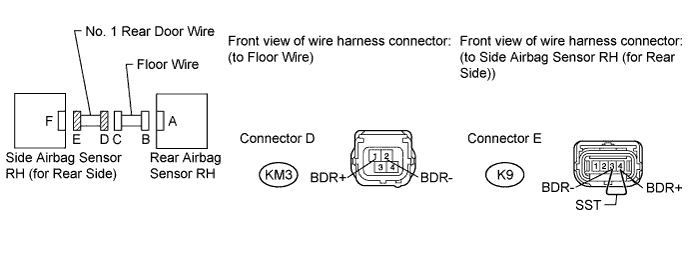
Disconnect the No. 1 rear door wire connector from the floor wire.
Tip:SST has already been inserted into connector E.
-
Measure the resistance according to the value(s) in the table below.
Standard Resistance Tester Connection Condition Specified Condition KM3-1 (BDR+) - KM3-2 (BDR-) Always Below 1 Ω Table 60. Result Result Proceed to OK C NG D
-
-
- Click here
CHECK WIRE HARNESS (SHORT)
-
for LHD:
-

Disconnect the No. 2 rear door wire connector from the No. 2 floor wire.
-
Measure the resistance according to the value(s) in the table below.
Standard Resistance Tester Connection Condition Specified Condition LN3-1 (BDL+) - LN3-2 (BDL-) Always 1 MΩ or higher Table 61. Result Result Proceed to OK A NG B
-
-
for RHD:
-
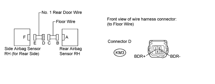
Disconnect the No. 1 rear door wire connector from the floor wire.
-
Measure the resistance according to the value(s) in the table below.
Standard Resistance Tester Connection Condition Specified Condition KM3-1 (BDR+) - KM3-2 (BDR-) Always 1 MΩ or higher Table 62. Result Result Proceed to OK C NG D
-
-
- Click here
CHECK WIRE HARNESS (SHORT TO B+)
-
for LHD:
-
Turn the engine switch off.
-
Disconnect the cable from the negative (-) battery terminal, and wait for at least 90 seconds.
-
Disconnect the No. 2 rear door wire connector from the No. 2 floor wire.
-
Connect the cable to the negative (-) battery terminal.
-
Turn the engine switch on (IG).
-
Measure the voltage according to the value(s) in the table below.
Standard Voltage Tester Connection Switch Condition Specified Condition LN3-1 (BDL+) - Body ground Engine switch on (IG) Below 1 V LN3-2 (BDL-) - Body ground Engine switch on (IG) Below 1 V Table 63. Result Result Proceed to OK A NG B
-
-
for RHD:
-
Turn the engine switch off.
-
Disconnect the cable from the negative (-) battery terminal, and wait for at least 90 seconds.
-
Disconnect the No. 1 rear door wire connector from the floor wire.
-
Connect the cable to the negative (-) battery terminal.
-
Turn the engine switch on (IG).
-
Measure the voltage according to the value(s) in the table below.
Standard Voltage Tester Connection Switch Condition Specified Condition KM3-1 (BDR+) - Body ground Engine switch on (IG) Below 1 V KM3-2 (BDR-) - Body ground Engine switch on (IG) Below 1 V Table 64. Result Result Proceed to OK C NG D
-
-
- Click here
CHECK WIRE HARNESS (SHORT TO GROUND)
-
for LHD:
-
Disconnect the No. 2 rear door wire connector from the No. 2 floor wire.
-
Measure the resistance according to the value(s) in the table below.
Standard Resistance Tester Connection Condition Specified Condition LN3-1 (BDL+) - Body ground Always 1 MΩ or higher LN3-2 (BDL-) - Body ground Always 1 MΩ or higher Table 65. Result Result Proceed to OK A NG B
-
-
for RHD:
-
Disconnect the No. 1 rear door wire connector from the floor wire.
-
Measure the resistance according to the value(s) in the table below.
Standard Resistance Tester Connection Condition Specified Condition KM3-1 (BDR+) - Body ground Always 1 MΩ or higher KM3-2 (BDR-) - Body ground Always 1 MΩ or higher Table 66. Result Result Proceed to OK C NG D
-
-
- Click here
CHECK NO. 2 FLOOR WIRE (OPEN)
-
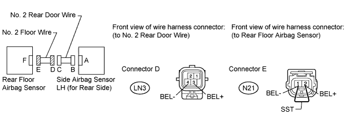
Disconnect the No. 2 floor wire connector from the No. 2 rear door wire.
Tip:SST has already been inserted into connector E.
-
Measure the resistance according to the value(s) in the table below.
Standard Resistance Tester Connection Condition Specified Condition LN3-3 (BEL+) - LN3-4 (BEL-) Always Below 1 Ω
- OKClick here
- NGClick here
-
- Click here
CHECK NO. 2 FLOOR WIRE (SHORT)
-
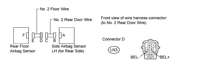
Disconnect the No. 2 floor wire connector from the No. 2 rear door wire.
-
Measure the resistance according to the value(s) in the table below.
Standard Resistance Tester Connection Condition Specified Condition LN3-3 (BEL+) - LN3-4 (BEL-) Always 1 MΩ or higher
- OKClick here
- NGClick here
-
- Click here
CHECK NO. 2 FLOOR WIRE (SHORT TO B+)
-
Turn the engine switch off.
-
Disconnect the cable from the negative (-) battery terminal, and wait for at least 90 seconds.
-
Disconnect the No. 2 floor wire connector from the No. 2 rear door wire.
-
Connect the cable to the negative (-) battery terminal.
-
Turn the engine switch on (IG).
-
Measure the voltage according to the value(s) in the table below.
Standard Voltage Tester Connection Switch Condition Specified Condition LN3-3 (BEL+) - Body ground Engine switch on (IG) Below 1 V LN3-4 (BEL-) - Body ground Engine switch on (IG) Below 1 V
- OKClick here
- NGClick here
-
- Click here
CHECK NO. 2 FLOOR WIRE (SHORT TO GROUND)
-
Disconnect the No. 2 floor wire connector from the No. 2 rear door wire.
-
Measure the resistance according to the value(s) in the table below.
Standard Resistance Tester Connection Condition Specified Condition LN3-3 (BEL+) - Body ground Always 1 MΩ or higher LN3-4 (BEL-) - Body ground Always 1 MΩ or higher
- OKClick here
- NGClick here
-
- Click here
CHECK NO. 1 REAR DOOR WIRE (OPEN)
-
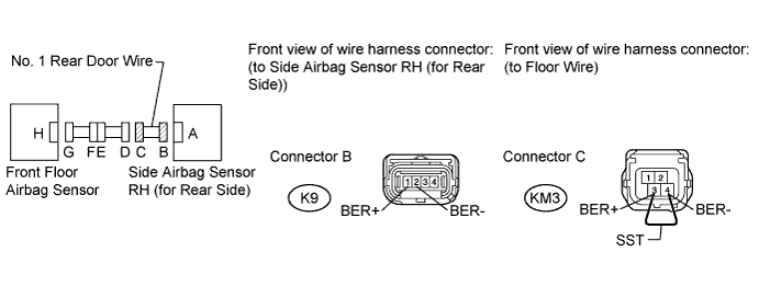
Disconnect the No. 1 rear door wire connector from the floor wire.
-
Using SST, connect terminals 3 (BER+) and 4 (BER-) of connector C.
Note:Do not forcibly insert SST into the terminals of the connector when connecting.
09843-18040 -
Measure the resistance according to the value(s) in the table below.
Standard Resistance Tester Connection Condition Specified Condition K9-1 (BER+) - K9-2 (BER-) Always Below 1 Ω
- OKClick here
- NGClick here
-
- Click here
CHECK FLOOR WIRE (OPEN)
-
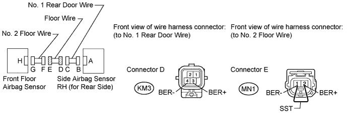
Disconnect the floor wire connector from the No. 2 floor wire.
-
Using SST, connect terminals 2 (BER+) and 1 (BER-) of connector E.
Note:Do not forcibly insert SST into the terminals of the connector when connecting.
09843-18040 -
Measure the resistance according to the value(s) in the table below.
Standard Resistance Tester Connection Condition Specified Condition KM3-3 (BER+) - KM3-4 (BER-) Always Below 1 Ω
- OKClick here
- NGClick here
-
- Click here
CHECK NO. 1 REAR DOOR WIRE (SHORT)
-
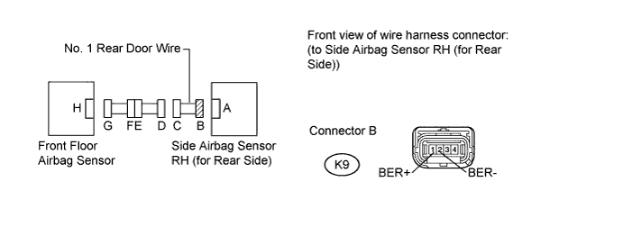
Disconnect the No. 1 rear door wire connector from the floor wire.
-
Measure the resistance according to the value(s) in the table below.
Standard Resistance Tester Connection Condition Specified Condition K9-1 (BER+) - K9-2 (BER-) Always 1 MΩ or higher
- OKClick here
- NGClick here
-
- Click here
CHECK FLOOR WIRE (SHORT)
-
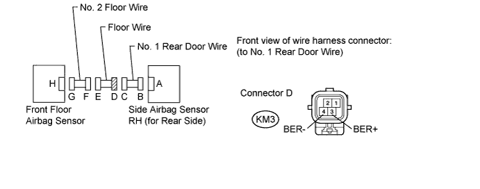
Disconnect the floor wire connector from the No. 2 floor wire.
-
Measure the resistance according to the value(s) in the table below.
Standard Resistance Tester Connection Condition Specified Condition KM3-3 (BER+) - KM3-4 (BER-) Always 1 MΩ or higher
- OKClick here
- NGClick here
-
- Click here
CHECK NO. 1 REAR DOOR WIRE (SHORT TO B+)
-
Turn the engine switch off.
-
Disconnect the cable from the negative (-) battery terminal, and wait for at least 90 seconds.
-
Disconnect the No. 1 rear door wire connector from the floor wire.
-
Connect the cable to the negative (-) battery terminal.
-
Turn the engine switch on (IG).
-
Measure the voltage according to the value(s) in the table below.
Standard Voltage Tester Connection Switch Condition Specified Condition K9-1 (BER+) - Body ground Engine switch on (IG) Below 1 V K9-2 (BER-) - Body ground Engine switch on (IG) Below 1 V
- OKClick here
- NGClick here
-
- Click here
CHECK FLOOR WIRE (SHORT TO B+)
-
Turn the engine switch off.
-
Disconnect the cable from the negative (-) battery terminal, and wait for at least 90 seconds.
-
Disconnect the floor wire connector from the No. 2 floor wire.
-
Connect the cable to the negative (-) battery terminal.
-
Turn the engine switch on (IG).
-
Measure the voltage according to the value(s) in the table below.
Standard Voltage Tester Connection Switch Condition Specified Condition KM3-3 (BER+) - Body ground Engine switch on (IG) Below 1 V KM3-4 (BER-) - Body ground Engine switch on (IG) Below 1 V
- OKClick here
- NGClick here
-
- Click here
CHECK NO. 1 REAR DOOR WIRE (SHORT TO GROUND)
-
Disconnect the No. 1 rear door wire connector from the floor wire.
-
Measure the resistance according to the value(s) in the table below.
Standard Resistance Tester Connection Condition Specified Condition K9-1 (BER+) - Body ground Always 1 MΩ or higher K9-2 (BER-) - Body ground Always 1 MΩ or higher
- OKClick here
- NGClick here
-
- Click here
CHECK FLOOR WIRE (SHORT TO GROUND)
-
Disconnect the floor wire connector from the No. 2 floor wire.
-
Measure the resistance according to the value(s) in the table below.
Standard Resistance Tester Connection Condition Specified Condition KM3-3 (BER+) - Body ground Always 1 MΩ or higher KM3-4 (BER-) - Body ground Always 1 MΩ or higher
- OKClick here
- NGClick here
-
- Click here
USE SIMULATION METHOD TO CHECKClick here
- Click here
REPLACE NO. 2 FLOOR WIRE
- Click here
REPLACE FLOOR WIRE
- Click here
REPLACE NO. 2 REAR DOOR WIRE
- Click here
REPLACE NO. 1 REAR DOOR WIRE
- Click here
REPLACE WIRE HARNESS
- Click here
REPLACE SIDE AIRBAG SENSOR LH (FOR FRONT SIDE)Click here
- Click here
REPLACE SIDE AIRBAG SENSOR RH (FOR FRONT SIDE)Click here
- Click here
REPLACE REAR AIRBAG SENSOR LHClick here
- Click here
REPLACE REAR AIRBAG SENSOR RHClick here
- Click here
REPLACE SIDE AIRBAG SENSOR LH (FOR REAR SIDE)Click here
- Click here
REPLACE SIDE AIRBAG SENSOR RH (FOR REAR SIDE)Click here
- Click here
REPLACE REAR FLOOR AIRBAG SENSORClick here
- Click here
REPLACE FRONT FLOOR AIRBAG SENSORClick here
- Click here
REPLACE CENTER AIRBAG SENSOR ASSEMBLYClick here