METER / GAUGE SYSTEM Odo/Trip Switch Malfunction
DESCRIPTION
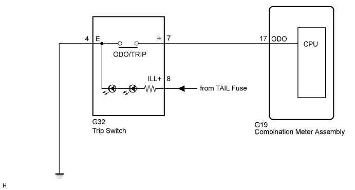
In this circuit, the combination meter assembly receives an ODO/TRIP switch signal from the trip switch using the direct line.
Tech Tips
The whole trip switch should be replaced if the ODO/TRIP switch has a malfunction because this part is not independently supplied.
WIRING DIAGRAM
INSPECTION PROCEDURE
PROCEDURE
-
READ VALUE USING INTELLIGENT TESTER (ODO/TRIP CHANGE SW)
-
Connect the intelligent tester to the DLC3.
-
Turn the engine switch on (IG).
-
Turn the tester on.
-
Enter the following menus: Body / Combination Meter / Data List.
-
Check the values by referring to the table below.
Combination Meter Tester Display Measurement Item/Range Normal Condition Diagnostic Note ODO/TRIP Change SW ODO/TRIP change switch condition OFF: ODO/TRIP change switch released - ON: ODO/TRIP change switch pressed - OK ODO/TRIP switch condition displayed on the tester changes with the actual switch operation.
NG 
CHECK HARNESS AND CONNECTOR (COMBINATION METER ASSEMBLY - TRIP SWITCH) Click here
OK 
REPLACE COMBINATION METER ASSEMBLY Click here
-
-
CHECK HARNESS AND CONNECTOR (COMBINATION METER ASSEMBLY - TRIP SWITCH)
-
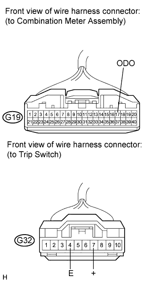
Disconnect the G19 and G32 connectors.
-
Measure the resistance according to the value(s) in the table below.
Standard Resistance Tester Connection Condition Specified Condition G19-17 (ODO) - G32-7 (+) Always Below 1 Ω G32-7 (+) - Body ground Always 10 kΩ or higher G32-4 (E) - Body ground Always Below 1 Ω
NG 
REPAIR OR REPLACE HARNESS OR CONNECTOR
OK 
-
-
INSPECT TRIP SWITCH (ODO/TRIP SWITCH)
-
Remove the trip switch Click here.
-
Measure the resistance according to the value(s) in the table below.
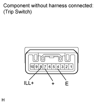
Standard Resistance Tester Connection Condition Specified Condition 4 (E) - 7 (+) ODO/TRIP switch is pressed Below 1 Ω 4 (E) - 7 (+) ODO/TRIP switch is released 10 kΩ or higher -
Apply battery voltage from the wire harness back side between the terminals of the switch, and check the lighting condition of the trip switch.
OK Tester Connection Condition Specified Condition Battery positive (+) → 8 (ILL+)
Battery negative (-) → 4 (E)
Always Trip switch illuminates
NG
REPLACE TRIP SWITCH Click here
OK
REPLACE COMBINATION METER ASSEMBLY Click here
-