METER / GAUGE SYSTEM Tachometer Malfunction
DESCRIPTION
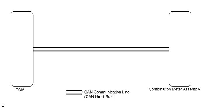
In this circuit, the meter CPU receives engine speed signals from the ECM using the CAN communication system (CAN No. 1 Bus). The meter CPU displays the engine speed calculated based on the data received from the ECM.
WIRING DIAGRAM
INSPECTION PROCEDURE
PROCEDURE
-
CHECK CAN COMMUNICATION SYSTEM
-
Check if a CAN communication DTC is output Click here.
Result Result Proceed to CAN communication DTC is not output. A CAN communication DTC is output. B
B 
GO TO CAN COMMUNICATION SYSTEM Click here
A 
-
-
PERFORM ACTIVE TEST USING INTELLIGENT TESTER (TACHO METER OPERATION)
-
Connect the intelligent tester to the DLC3.
-
Turn the engine switch on (IG).
-
Turn the tester on.
-
Enter the following menus: Body / Combination Meter / Active Test.
-
Check the operation by referring to the table below.
Combination Meter Tester Display Test Part Control Range Diagnostic Note Tacho Meter Operation Tachometer OFF, 0, 1000, 2000, 3000, 4000, 5000, 6000, 7000 (rpm) Confirm that the vehicle is stopped with the engine idling OK Tachometer indication is normal.
NG
REPLACE COMBINATION METER ASSEMBLY Click here
OK
-
-
READ VALUE USING INTELLIGENT TESTER (ENGINE RPM)
-
Connect the intelligent tester to the DLC3.
-
Turn the engine switch on (IG).
-
Turn the tester on.
-
Enter the following menus: Body / Combination Meter / Data List.
-
Check the values by referring to the table below.
Combination Meter Tester Display Measurement Item/Range Normal Condition Diagnostic Note Engine Rpm Engine speed/Min.: 0 rpm, Max.: 12750 rpm 650 to 750 rpm (When idling) If data received from the ECM exceeds the range that can be displayed on the meter, the meter continues to display the maximum value of the range. OK Engine speed displayed on the tester is almost the same as the tachometer indication.
NG
REPLACE COMBINATION METER ASSEMBLY Click here
OK
-
-
READ VALUE USING INTELLIGENT TESTER (ENGINE SPEED)
-
Connect the intelligent tester to the DLC3.
-
Turn the engine switch on (IG).
-
Turn the tester on.
-
Enter the following menus: Powertrain / Engine and ECT / Data List.
-
Check the values by referring to the table below.
Engine and ECT Tester Display Measurement Item/Range Normal Condition Diagnostic Note Engine Speed Engine speed/Min.: 0 rpm, Max.: 16383.75 rpm 650 to 750 rpm (When idling) - OK Engine speed displayed on the tester is almost the same as the intelligent tester indication (Body / Combination Meter / Data List). Result Result Proceed to OK A NG (for 2GR-FE) B NG (for 2AZ-FE) C
B
GO TO SFI SYSTEM (for 2GR-FE) Click here
C
GO TO SFI SYSTEM (for 2AZ-FE) Click here
A
-
-
REPLACE ECM
-
Replace the ECM with a new or a known good one Click here for 2GR-FE, Click here for 2AZ-FE).
OK The operation of the tachometer returns to normal.
NG
REPLACE COMBINATION METER ASSEMBLY Click here
OK 
END
-